5 Your new television
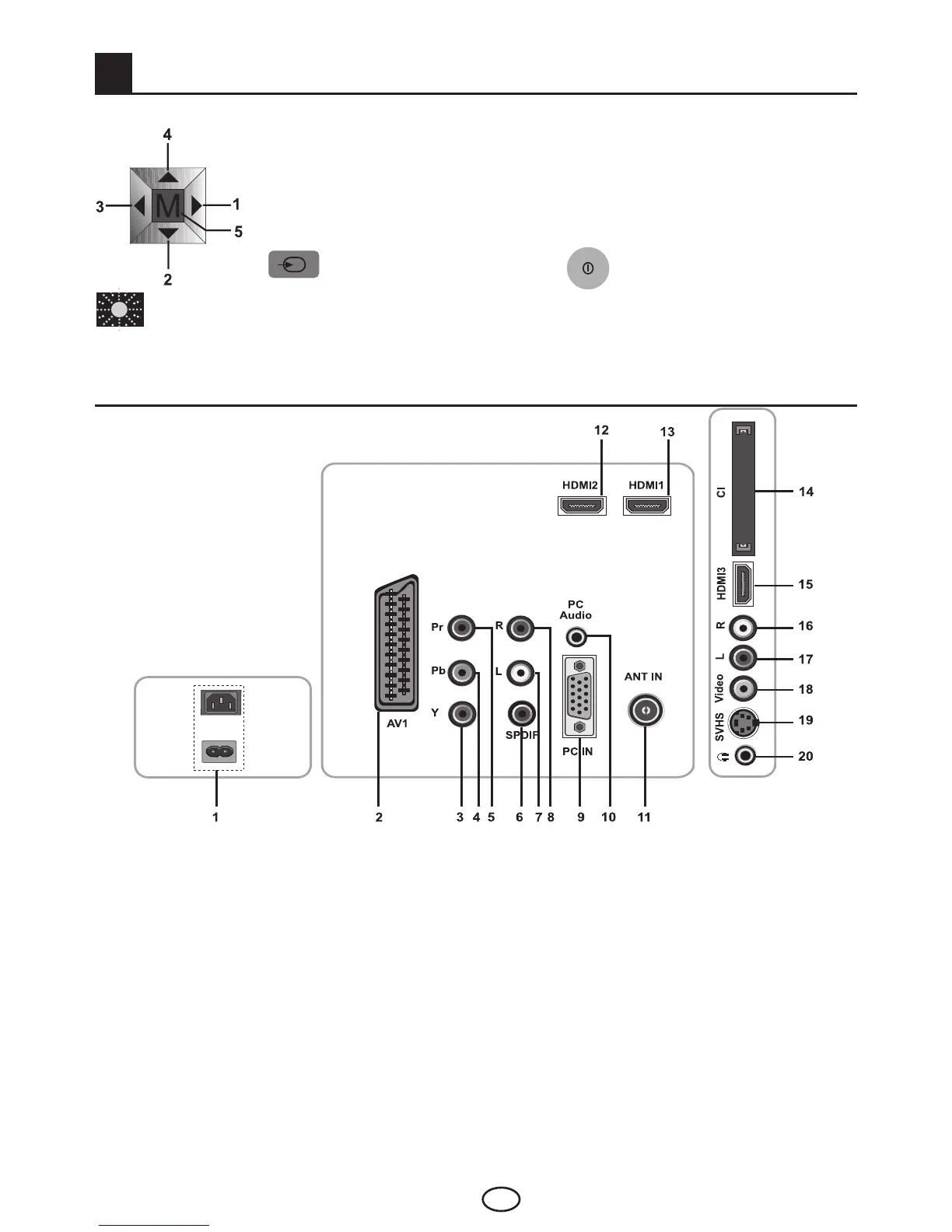
5.1-TV Control Panel
1-Rightmovementinmenu/Volumedownbutton
2-Downmovementinmenu/Programdownbutton
3-Leftmovementinmenu/VolumeUpbutton
4-Upmovementinmenu/Programupbutton
5-Confirminmenu/Menubutton
Source Menu button MainPowerOn/Offbutton
Stand by indicator
Bright light: TV is in Stand-by
Dimmed light: TV is On
No light: Power switch is off.
5.2-Rear and Side External Connections
1 Power input
2 AV1 input
3 Component video input (Y)
4 Component video input (Pb)
5 Component video input (Pr)
6 SPDIF Digital audio output
7 Component audio input (L)
8 Component audio input (R)
9 VGA (PC connection) input
10 PC audio input
11 Antenna input
12 HDMI 2 input
13 HDMI 1 input
14 CI slot input
15 HDMI 3 input (*)
16 Sound input CINCH connector (Right/R)
17 Audio input CINCH connector (Left/L)
18 Video input CINCH connector
19 S-Video input
20 Stereo Headphone socket
(*):Thesefeaturesareoptionalandtheyarenotavailableonallmodels.
• Abovedrawingforexternalconnectionsisrepresentational.TheirorderandplacesonyourTV
may be different.
• PleaseseeTechnicalSpecificationsTableonpage31fortheavailableexternalconnectionson
your television.
or



 To Next Page