EasyManua.ls Logo

Sencore TF151 - User Manual

Default Icon
24 pages
Print Icon
To Next Page IconTo Next Page
Loading...
IF
151
IN-CIRCUIT
FET
AND
TRANSISTOR
TESTER
ill
m
z
o
o
]
m
MANUAL
Question and Answer IconNeed help?

Do you have a question about the Sencore TF151 and is the answer not in the manual?

Summary

Safety Precautions

Specifications

Regular Transistor Specifications

Details AC beta (hfe) measurements at 60 Hz for different ranges.

Field Effect Transistor Specifications

Details Transconductance (Gm) measurements at VDS=5V, VGS=0.

Common Transistor Terminology

TF151 Controls Overview

Selection Switches

Combines POL/MAT, BIAS, and FUNCTION switches for selecting test parameters.

Calibration and Test Buttons

Includes BETA CAL, GAIN, and IDSS buttons for testing and calibration.

Test Jacks and Connections

Transistor Chart Columns Explained

Explains columns like Transistor Number, Test Position, and Polarity/Material.

FET Reference Book Section

FET Chart Columns Explained

Details columns for FETs like FET number, Channel, Bias, IDSS, and Gm.

Testing Regular Transistors

Beta and Leakage Parameters

Explains beta (hfe) and ICBO leakage testing for bipolar transistors.

Checking Regular Transistor AC Beta

Testing Connections and Setup

Details lead connections and function/type switch settings for transistor testing.

Regular Transistor Troubleshooting Chart

Checking Regular Transistor Leakage (ICBO)

Leakage Measurement Procedure

Steps for connecting leads, setting switches, and reading leakage.

Testing Field Effect Transistors (FETs)

FET Modes of Operation

Measuring FET Transconductance (Gm)

Gm Measurement Setup and Procedure

Steps for connecting leads, setting switches, zeroing, and reading Gm.

FET Troubleshooting Chart

Checking FET Gate Leakage (IGSS)

IGSS Leakage Measurement

Steps for connecting leads, setting switches, and reading leakage.

Zero Bias Drain Current (IDSS) Testing

IDSS Impact and Example

Explains IDSS role in circuits and provides a dissipation calculation example.

Dual Gate FET Testing

Dual FETs (Matched Pairs)

MOSFET;IGFET Safety Precautions

Handling and Testing Precautions

Covers body potential, lead handling, soldering iron grounding, and power cycling.

Matching Components

Transistor Substitution Guidance

Checking Diodes and Rectifiers In-Circuit

In-Circuit Diode Test Procedure

Steps for connecting leads, setting switches, and interpreting results for in-circuit diode tests.

Checking Diodes and Rectifiers Out of Circuit

Out-of-Circuit Diode Test Procedure

Steps for connecting leads, setting switches, and comparing forward/reverse current.

Zener Diode Testing

Varicap Diode Testing

Other Semiconductor Devices

Solid State Servicing Hints

Disassembly Instructions

TF151 Calibration

Leakage Calibration Procedure

Step-by-step guide to calibrate the leakage measurement.

Gm Calibration Procedure

Step-by-step guide to calibrate the Gm measurement.

Circuit Description

TF151 Troubleshooting Chart

TF151 Parts List

Included Items

Service and Warranty Information

Overview

The Sencore TF151 is an in-circuit FET and transistor tester, designed for dynamic testing of both regular (bipolar) transistors and Field Effect Transistors (FETs) in and out of circuit. It also checks diodes and rectifiers.

Function Description

The TF151 measures AC beta for regular transistors, Gm (transconductance) for FETs, and leakage for both types. It can also check diodes in or out of circuit. The device is designed to simplify transistor and FET testing for service technicians and industrial applications.

Important Technical Specifications

Regular Transistor (Bi-polar) Testing:

  • Beta (hfe) measured at 60 Hertz:
    • Lo Power X1: Beta 1-50, Ic 2.0 Ma
    • Lo Power X10: Beta 10-500, Ic 2.0 Ma
    • Hi Power X1: Beta 1-50, Ic 20 Ma
    • Hi Power X10: Beta 10-500, Ic 20 Ma
    • Special RF X1: Beta 1-50, Ic 0.2 Ma
  • Leakage (ICBO) measured at VCB=4V, IE=0:
    • One range: 0-100 microamps (lower 1/2 of scale)
    • 100-5000 microamps (upper 1/2 of scale)

Field Effect Transistors:

  • Transconductance (Gm) measured at VDS = 5V, VGS = 0:
    • X1 Range: 0-5000 Micromhos
    • X10 Range: 0-50,000 Micromhos
  • Gate Leakage (IGSS) measured at VGS = 4V, VDS = 0:
    • One range: 0-100 microamps (lower 1/2 of scale)
    • 100-5000 microamps (upper 1/2 of scale)
  • Zero Bias Drain Current (IDSS) measured at VDS = 5V, VGS = 0.

General:

  • Electrical: 105/130 VAC, 50/60 Hertz at 10 watts
  • Physical: 9 1/2" High x 7 1/2" wide X 6" deep
  • Weight: 9 pounds
  • Meter: Large 6-inch meter for easy reading.

Usage Features

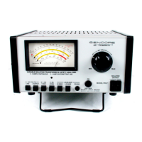
The TF151 features a large 6-inch meter for easy reading. It includes various controls for specific tests:

  • 'N' CHAN/NPN - 'P' CHAN/PNP Switch: Selects polarity for transistor/FET testing and diode forward/reverse currents.
  • Gm ZERO and BETA CAL Control: Adjusts for internal impedance differences in transistors to ensure accurate beta or Gm readings.
  • GAIN button: Used for beta and Gm checks, not for leakage.
  • IDSS Button: Used for zero bias drain current checks and matching/pairing FETs.
  • BIAS Switch: Selects NORM bias for depletion-type FETs or POS for enhancement-type FETs.
  • FUNCTION SWITCH: Selects tests for regular transistors or FETs.
  • ON-OFF Switch: Controls AC power and acts as a pilot light.

Test leads are provided for Source/Emitter (black), Gate 1/Base (yellow), Drain/Collector (red), and Gate 2 (blue, for dual gate FETs).

The accompanying Sencore FET and Transistor Reference Book is a key feature, providing comprehensive information on transistor and FET types, including:

  • Transistor Section: Indicates transistor number, proper function switch position (LO POWER, HI POWER, SPECIAL RF), polarity/material (NPN/PNP, Germanium/Silicon), base diagram, GAIN (BETA) with min/ave/max figures, and maximum LEAKAGE (ICBO).
  • FET Section: Lists FET number, channel type (N/P), BIAS switch setting (NORM/POS), base diagram, IDSS MAX MA, GAIN Gm (uMHOS) with min/ave/max figures, and LEAKAGE IGSS MAX uA.

The manual provides detailed instructions for connecting and testing various devices:

  • Regular Transistors (Bi-polar): Checks AC beta (hfe) and leakage (ICBO) in or out of circuit. Includes a trouble chart for common issues like open leads, shorts, and interchanged leads.
  • Field Effect Transistors (FETs): Measures Gm (transconductance) and gate leakage (IGSS) in or out of circuit. Explains depletion and enhancement modes and how to set the BIAS switch. Includes a trouble chart for FET issues.
  • Zero Bias Drain Current (IDSS): Used for matching and culling FETs, crucial for balanced circuits and cascode amplifiers.
  • Dual Gate Field Effect Transistors: Can be checked for Gm on both gates and leakage on the second gate.
  • Dual Field Effect Transistors: Allows checking and comparing two FETs in one package for matching.
  • Diodes and Rectifiers: Checks for open or shorts in-circuit and measures forward/reverse current out of circuit to determine front-to-back ratio.
  • Zener Diodes: Can be checked, but results may not indicate the regulating point.
  • Varicap Diodes: Appear as regular silicon diodes; reverse leakage is a critical check.

Maintenance Features

The TF151 is designed for easy recalibration and repair.

  • Disassembly: The unit can be easily removed from its case by unscrewing four screws, exposing the internal calibration controls.
  • Calibration:
    • Leakage Calibration: Involves connecting an external milliammeter and adjusting the LEAKAGE CAL control to match a 1 milliamp reading.
    • Gm Calibration: Requires an oscilloscope connected to the S or source jack and G1 or gate jack. The Gm CAL control is adjusted to achieve a 0.34 volts peak-to-peak square wave signal.
  • Trouble Chart: A comprehensive trouble chart helps diagnose issues with the TF151 itself, divided into sections for regular transistor, FET, and leakage. It lists symptoms, probable causes (e.g., open resistors, shorted diodes/capacitors, faulty transistors), and corrective measures.
  • Parts List and Schematic: The manual includes a detailed parts list and schematic diagram for easier repair and component replacement.
  • Warranty and Service: Sencore provides a 90-day warranty. For out-of-warranty service, units can be sent directly to the factory service department. Replacement parts can be ordered from the factory.

Safety Precautions: The manual emphasizes safety, advising the use of an isolation transformer, discharging capacitors, avoiding contact with high voltages, and not working alone on hazardous circuits. Specific precautions are given for handling MOSFETs/IGFETs due to their sensitivity to static charges.

Sencore TF151 Specifications

General IconGeneral
BrandSencore
ModelTF151
CategoryTest Equipment
LanguageEnglish

Related product manuals