9
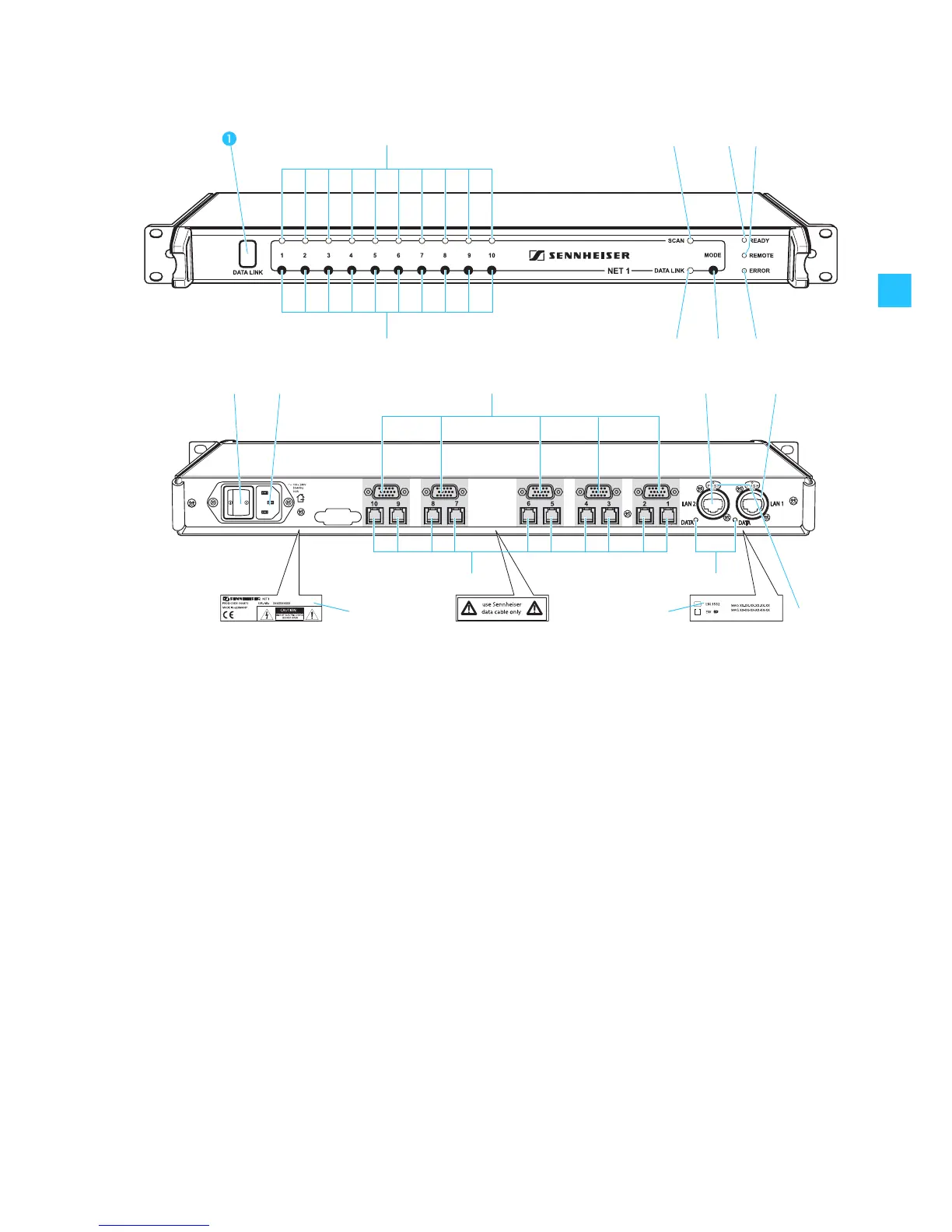
Operating controls
Infra-red interface (DATA LINK),
backlit in blue
“CHANNEL” LED (1 to 10), green
쐋 “SCAN” LED, yellow
“READY” LED, green
“REMOTE” LED, yellow
“ERROR” LED, red
MODE button
“DATA LINK” LED, yellow
Channel buttons (1 to 10)
ON/OFF switch
3-pin IEC power connector
5 x sub-D socket for connecting
EM 3532 twin receivers
LAN 2 Ethernet connection, Neutrik RJ 45 socket
LAN 1 Ethernet connection, Neutrik RJ 45 socket
“DATA” LED, yellow (Ethernet)
10 x RJ 10 socket for connecting rack-mount receivers
or transmitters (IEM) of the evolution wireless G2
series
Type plate
Plate with MAC addresses
Latch for Ethernet connection
(when using the matching Neutrik plug)