Do you have a question about the Sennheiser SK 300 G2 and is the answer not in the manual?
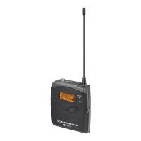
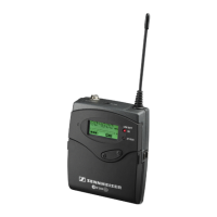
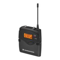
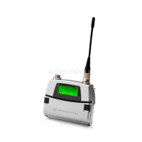
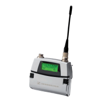
Identifies and describes physical controls and indicators on the transmitter.
Describes symbols and elements shown on the transmitter's display.
Covers power, voltage, dimensions, and compliance details.
Details Audio Frequency transmission performance and specifications.
Details Radio Frequency transmission performance and specifications.
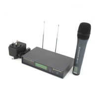
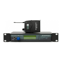
Lists essential equipment and tools for testing and alignment procedures.
Provides diagrams and descriptions for measurement and alignment setups.
Details specialized tools required for service operations and their part numbers.
Outlines specific tests, measurements, and required values for device verification.
Procedures for reading/modifying device data using the infrared adaptor.
High-level diagram of the transmitter's functional units.
Detailed schematic of the mainboard, section one of three.
Detailed schematic of the mainboard, section two of three.
Detailed schematic of the mainboard, section three of three.
Detailed schematic of the RF board, section one of two.
Detailed schematic of the RF board, section two of two.
Pin assignment for the mainboard's flexible connector, section one of two.
Pin assignment for the mainboard's flexible connector, section two of two.
Pin assignment for the RF board's connector.
Component layout view of the mainboard's printed circuit board.
Solder side view of the mainboard's printed circuit board.
Component layout view of the RF board's printed circuit board.
Solder side view of the RF board's printed circuit board.
| Type | Bodypack Transmitter |
|---|---|
| Modulation | Wideband FM |
| Total Harmonic Distortion | < 0.9% |
| Pilot Tone Frequency | 32.768 kHz |
| Battery Life | Up to 8 hours |
| Operating Time | 8 hours |
| Dimensions | 82 x 64 x 24 mm |
| RF Output Power | 30 mW |
| Power Supply | 2 x AA batteries |
| Connector | 3.5mm mini-jack |
| Input Connector | 3.5 mm jack |
| Max. Frequency Deviation | ± 48 kHz |