Product overview
RS 185 | 7
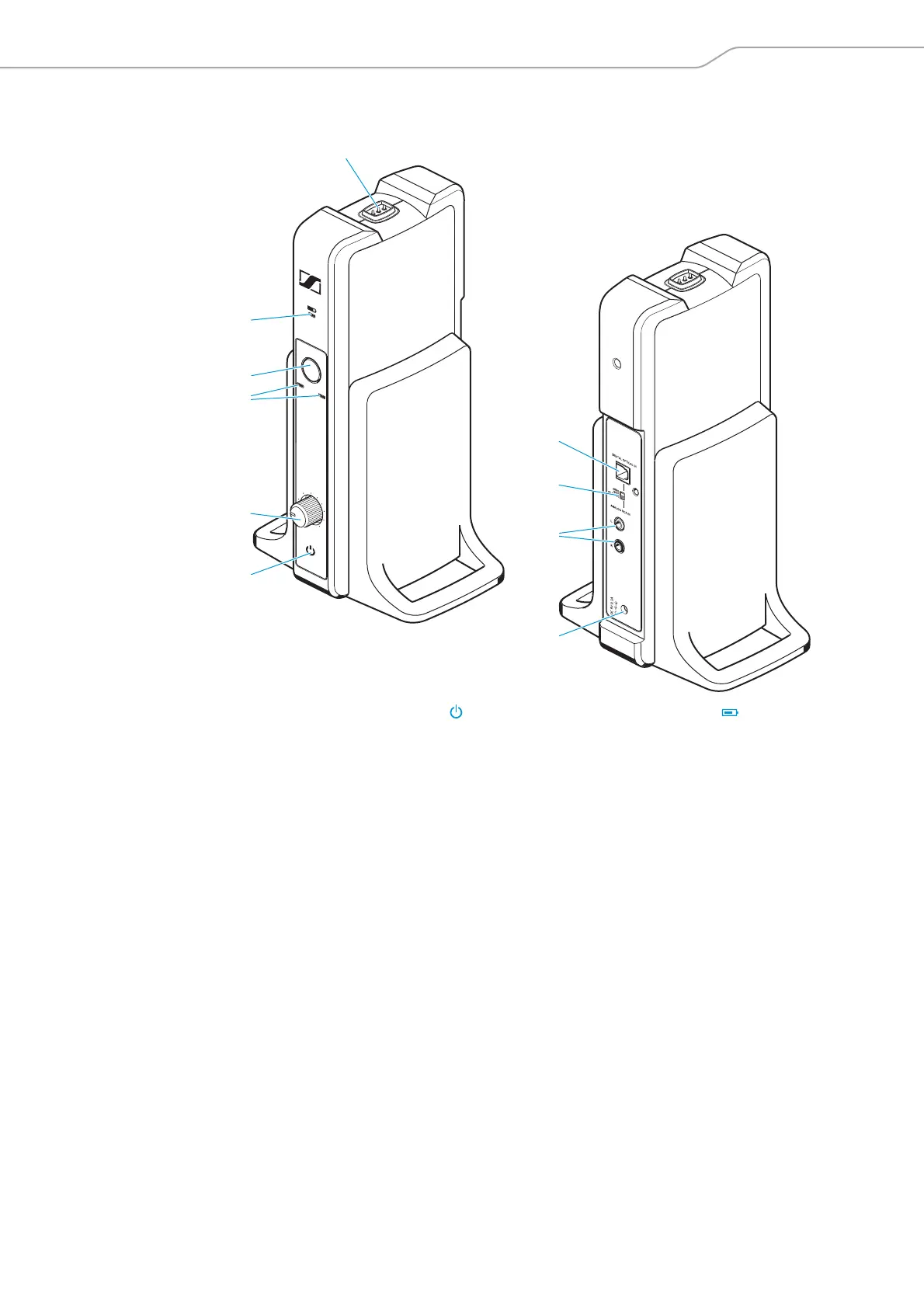
Overview of the TR 185 transmitter
MLC
ALC
LEVEL
MLC
MAX
MIN
6
2
1
4
5
3
7
8
9
0
1 TR status LED
2 MLC rotary knob,
fo
r manual level control adjust-
ment
3 ALC, MLC LEVE
L LEDs, indicate
the selected signal level control
4 LEVEL button
t
o toggle between manual and
automatic level controls
5 Charge status LED
6 Charging contacts
7 DIGITAL OPTICAL IN Digita
l opti-
cal audio input
8 AUDIO INPUT SELECTION switch,
for digital or an
alog audio input
selection
9 L, R RCA audio input,
for analog audio input
0 DC 9V
0.3A socket for
the power
supply unit