MT4412E Rev.2 15/10/2019 Pagina 14 di 30
Detectors with 4-20mA output
Detectors with 4-20mA analogue output are either connected to the gas control unit, directly on
the main board or via one remote 8-input STG/IN8-S module. The module may be connected
remotely to the gas control unit. For connection, a detector with a 4-20mA analogue output
requires a 3-conductor cable: 2 conductors for the power supply (usually from 12 to 28 Vdc -
refer to the gas detector technical manual) and one conductor for the 4-20mA signal. The
generally recommended cable is a shielded 3 x 0.75, which allows up to 100 meters between
the gas detector and STG/IN8-S input module
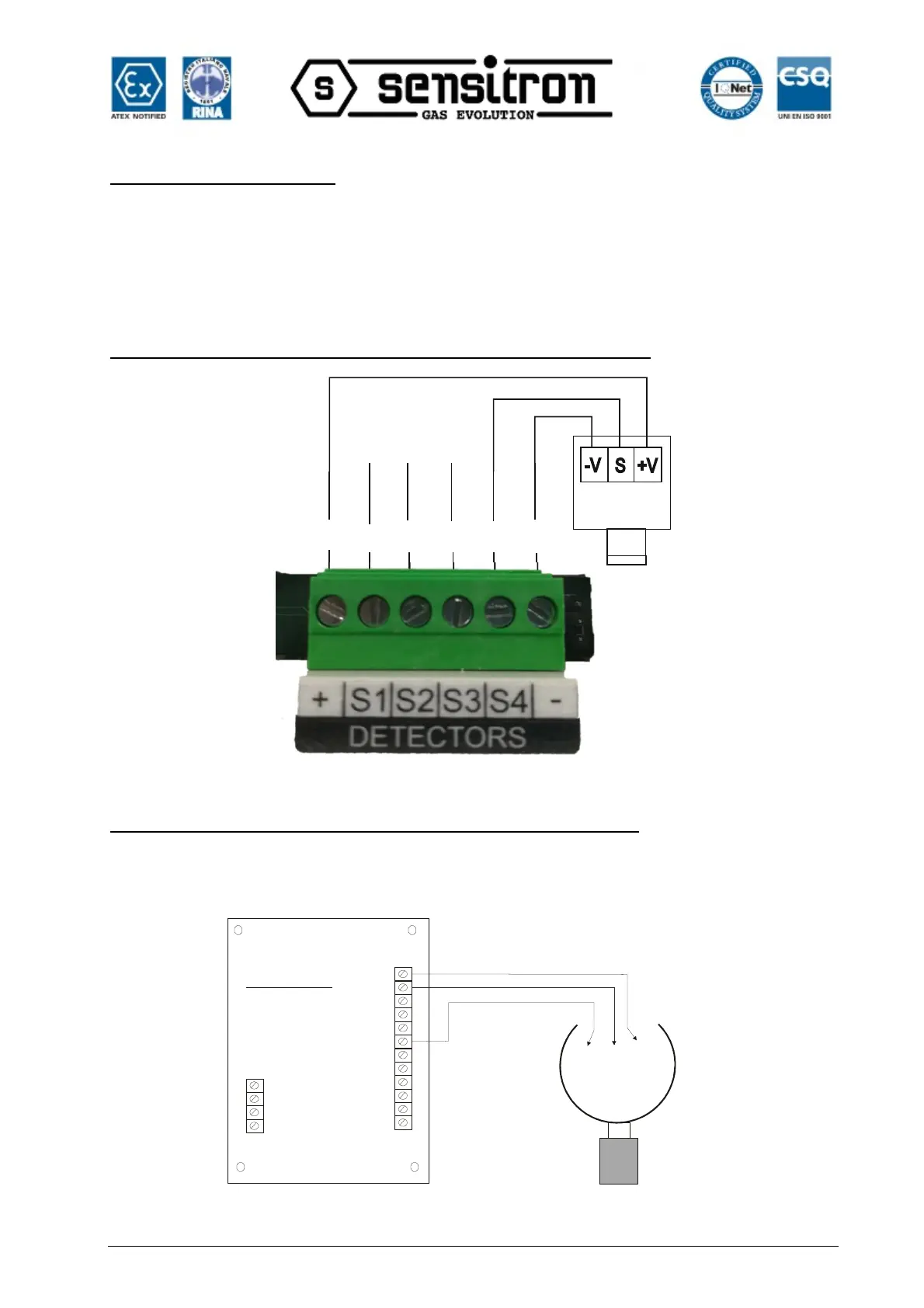
Detectors with 4-20 mA output directly connected to the gas control unit
Fig. 2.2.1 a) Connection of the 8 detectors of the gas control unit
Detectors with a 4-20 mA output connected to the ST.G/IN8-S module
The following diagram shows the connection of a gas detector with a 4-20 mA output to a
STG/IN8-S input module. During system start-up, make sure that each gas detector reaches a
minimum voltage of 12 Vdc.