Page 49
.
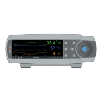
Controls, Indicators and Alarms
The Alarm Status Icon
8
indicates the ranking of the
highest priority alarm condition (flashing white triangle with
curved line and exclamation mark on red background in a
high priority alarm condition; flashing black triangle with
curved line and exclamation mark on yellow background in
a medium priority alarm condition; black triangle with
curved line and exclamation mark on cyan background in a
low priority alarm condition; light grey check mark symbol
on dark-grey background if no alarm condition).
On the very right
9
, the Status Bar usually indicates the
monitor’s date/time in the ‘yyyy-mm-dd hh:mm:ss’ format. On
measurement screens (p. 31), the date/time indication is
replaced by the V-Check™ Down-Counter (format hh:mm:ss)
in V-Check™ Mode (p. 35). This down-counter indicates the
duration of the V-Check™ Measurement if the V-Check™ Mea-
surement has not yet been started, the remaining time to fin-
ish the V-Check™ Measurement during an ongoing V-Check™
Measurement, and 00:00:00 once the V-Check™ Measurement
is finished. If the SDMS is not ready for use, it indicates --:--:--.
Good to know!
The date/time of the SDM can be adjusted in the menu; or, by
using V-STATS™, it is possible to set the SDM’s date/time to
the current date/time of the PC (i.e. to synchronize the date/
time setting of the SDM and the PC).
The ‘Sensor Temperature’ Icon
4
indicates the measured
sensor temperature (°C) and the current setting of SITE
PROTECTION. A ‘red-blue rightward arrow with tip down’
appears if SITE PROTECTION is ON, a ‘red rightward arrow’ if it
is OFF. The ‘Sensor Temperature’ Icon is marked yellow during
INITIAL HEATING, blue if SITE PROTECTION has reduced
the sensor temperature and red if the SDMS’ temperature
surveillance detected a sensor temperature-related problem.
On measurement/menu screens, position
5
either displays
the ‘Absolute Heating Power’ (AHP), the ‘Relative Heating
Power’ (RHP), both in mW, or no icon if Heating Power Mode
is OFF, whereas position
5
displays the ‘Gas Icon’ on the
‘Calibration Screen’. The ‘Gas Icon’ indicates the remaining
capacity of the Service Gas Bottle in %. It is marked yellow if
the remaining capacity is below 10% and red if the gas bottle
is empty (format: xxx%).
Note: On measurement/menu screens with RHP online trends,
no icon is displayed at position
5
.
The Status Text Field
6
in the middle displays Status Messages
(alarm/information messages). If there is no current Status
Message, the name of the presently active menu is displayed
in the status text field of menu screens and – during remote
monitoring via V-CareNeT™ – the ‘Patient Info’ is displayed in
the status text field of measurement screens.
The AUDIO Status Icon
7
on the right of the status text field
indicates the status of the SDM’s auditory alarm signals (ON,
PAUSED, OFF).