EasyManua.ls Logo

Sentinel BM-50 - Power Supply Connection

Sentinel BM-50
12 pages
Print Icon
To Next Page IconTo Next Page
To Previous Page IconTo Previous Page
Loading...
Color
Function
Description
versions
Red-blue
PIR
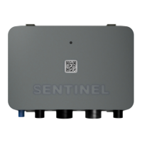
Digital input 4 - PIR sensor**
Standard and Pro
Pink
VIN3
Voltage input 3 - Engine battery (starboard)
Lite, Standard and Pro
White-green
RS485_N
RS-485 A (-)*
Standard and Pro
Grey-brown
GND
Ground
Standard and Pro
White-yellow
RS485_P
RS-485 B (+)*
Standard and Pro
Pink-grey
RS232_RX
RS-232 Rx*
Pro only
White-grey
Relay Common
Relay Common
Standard and Pro
Green-brown
RS232_TX
RS-232 Tx*
Pro only
White
Relay 2
Relay 2 Contact
Pro only
Yellow-brown
Unused
unused
Grey
Relay 1
Relay 1 Contact
Standard and Pro
* contact Sentinel for more information on supported protocols
** bilge, door, PIR and shore power inputs can be changed to other digital sensor types. Use Web or Mobile App to
change sensor type from their default values
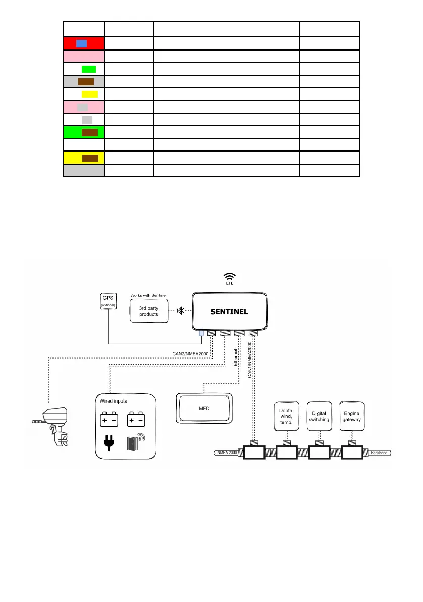
Typical installation block diagram is shown below
2.4 Power supply connection
To ensure continuous monitoring, the device should be connected to a constant power source. When connecting
any power or voltage input directly to the battery, it is important to protect the battery and electrical circuit from
6