DEFAULT DIGITAL INPUT CONFIGURATIONS
A: Purple - bilge sensor: used for float switch or bilge pump activity detection as shown in fig. 2.5A.
The input uses ACTIVE HIGH logic by default. If active low logic is required please contact support.
B: Green - door sensor: used for door alerts. Connect magnetic switch as shown in fig. 2.5B. The input uses ACTIVE
LOW logic by default (switch open when the door is open). If active high logic is required please contact support.
C: Blue - shore power presence detection: used for alerts on shore power disconnection. Connect a step-down
transformer (not included) as shown in fig. 2.5C.
D: Red-Blue - Motion sensor (PIR), used for detecting motion events on a boat. The input uses ACTIVE HIGH logic by
default. If active low logic is required please contact support.
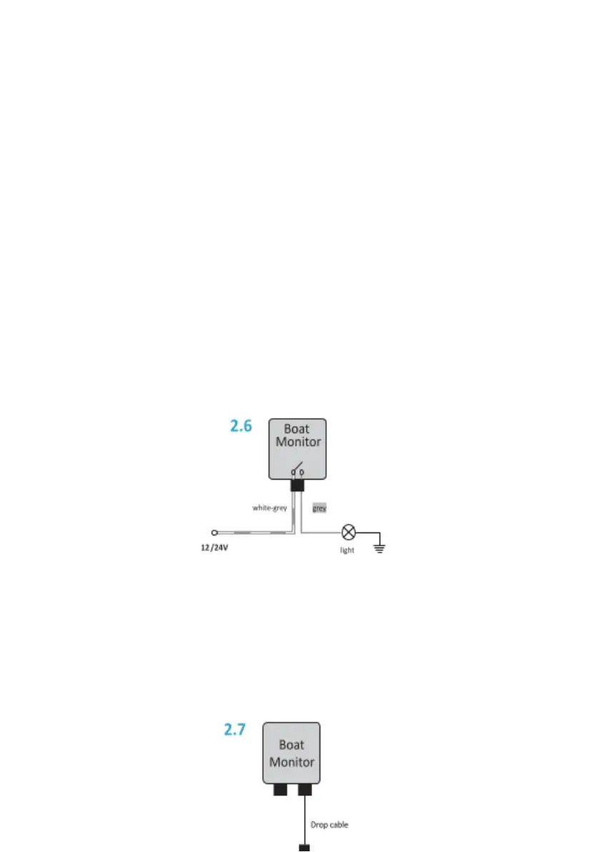
2.6 Relay output (Pro and Standard version only)
The Standard version has one built-in low power relay while the Pro version has two. In the Pro version, one contact
of both relays is connected to the Relay Common wire. The other side of the first relay is connected to the gray
wire, and the other side of the second relay is connected to the white wire. To ensure proper functioning, the
current must not exceed 1 A on each relay. The maximum allowed switching voltage is 60 V. For switching loads that
require more power, an additional power relay is needed.
Example: switching low power LED light with Boat monitor.
2.7 NMEA 2000® connection (Pro and Standard version only)
Boat monitor BM-50 is equipped with two CAN interfaces. CAN1 / NMEA2000 connector is a primary NMEA 2000
interface that connects to the boat instrument NMEA2000 backbone. CAN2 interface is a multipurpose CAN
interface (Pro version only). Contact Sentinel support for more information. Connect the CAN1 connector to the
NMEA 2000® backbone (bus) via a drop cable and T-connector. Important: Boat Monitor cannot be powered from
the NMEA 2000® backbone.
 Loading...