Sentry AutoVREL Flow Controller 13
Carefully route wire harnesses into wireways, making sure that they do not interfere with gears
during normal operation.
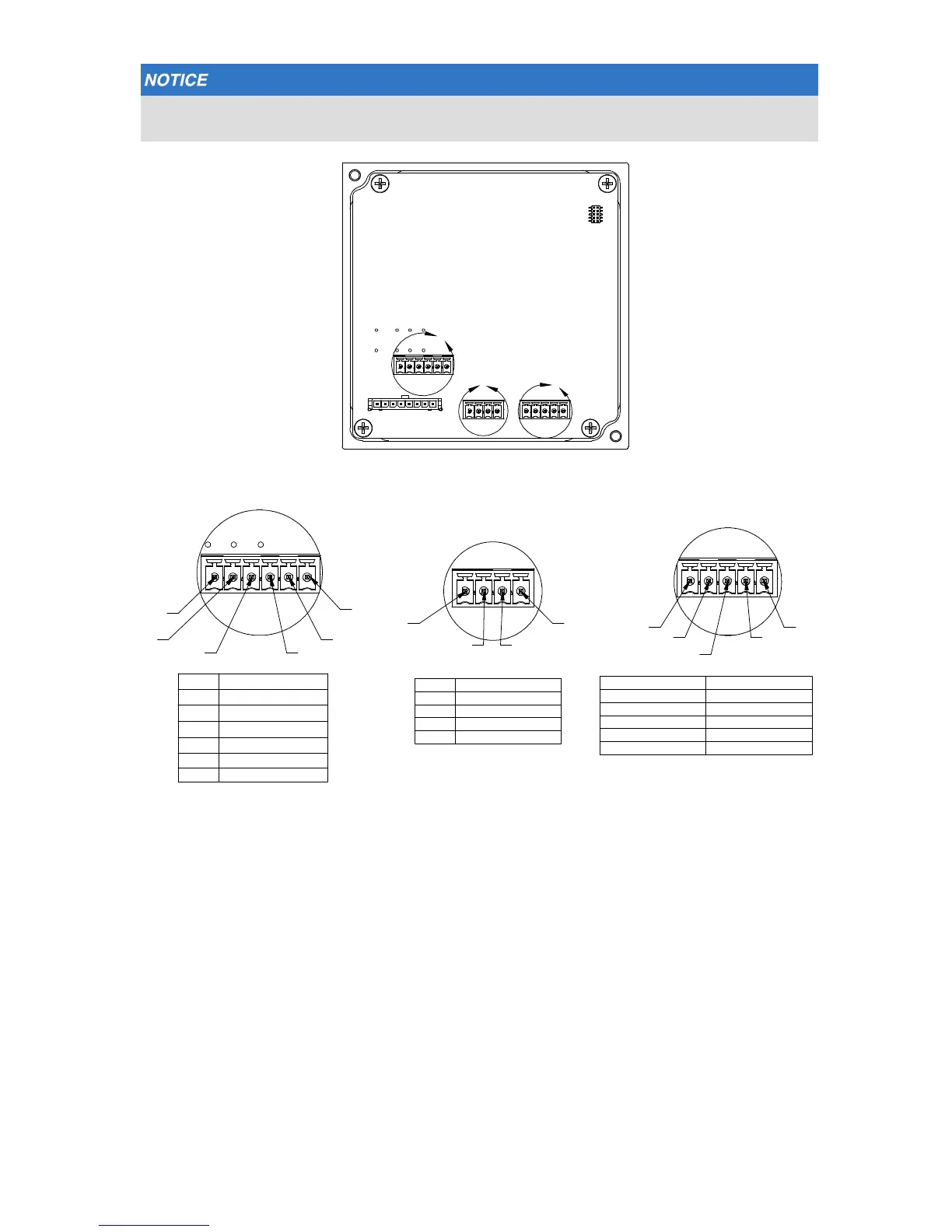
19. Feed the customer I/O harness and DC power supply harness through the cable
gland and cableway in the drive unit until they are exposed on the back side of the
panel.
20. Optional plant control system alarm: The AutoVREL ow controller features a relay
output that can be used to alarm the plant control system with a hard failure alarm.
During Alarm condition, the normally open contact will be open and the normally
closed contact will be closed. One wire from the DCS must be connected to RELAY
COM and the othe rwire either to RELAY NC or RELAY NO. (See detail C above.)
21. With all of the harnesses connected, reinstall the AutoVREL ow controller and
tighten in place using the 9/64-inch Allen wrench.
22. Wire the TSV IN connection (Alarm Conn: Detail C pin 4) to the TSV switch “normally
closed” and the GND (Alarm Conn: Detail C pin 6) to the TSV switch “common.”
LOC. PWR Conn
1 +24 VDC
2 GND
3 MODBUS +
4 MODBUS -
LOC. Alarm Conn
1 RELAY COM
2 RELAY NC
3 RELAY NO
4 TSV IN
LOC. Flow Meter Conn
1 +24 VDC
2 +12 VDC
3 GND
4 4-20 mA in
5 0-5 VDC in
C
D
E
5 RESERVE
6 GND
Detail C
Scale 3:1
Detail D
Scale 3:1
Detail E
Scale 3:1
1
2
3 4
5
6
1
1
2
2
3
3
4
4
5