Sentry AutoVREL Flow Controller 9
Installation
Unpacking
After carefully removing the Sentry AutoVREL ow controller and ow meter from its
shipping carton, inspect it for any damage. Report damages to the shipper immediately.
Mounting
 NOTE
Installation by a Sentry authorized service representative is recommended due to the complex
mechanical and electrical assembly needed.
Equipment Needed
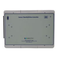
Sentry AutoVREL ow controller
– controller and drive unit
– ow meter
– wire harnesses – DC power (4-pin connector) and I/O harness (8-pin connector)
– shaft adapter, set screw and locking nut
Corded power drill
Cutting oil
Loctite Blue 242 or equivalent
Hammer
1/8-inch, 3/16-inch and 9/64-inch Allen wrenches
7/16-inch and 1/2-inch open-end, crescent or socket wrench or equivalent
Sentry AutoVREL mounting kit
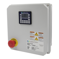
Sentry TSV thermal shuto valve and TSV switch (may already be on panel)
24 VDC power supply (only required if not available on existing panel)
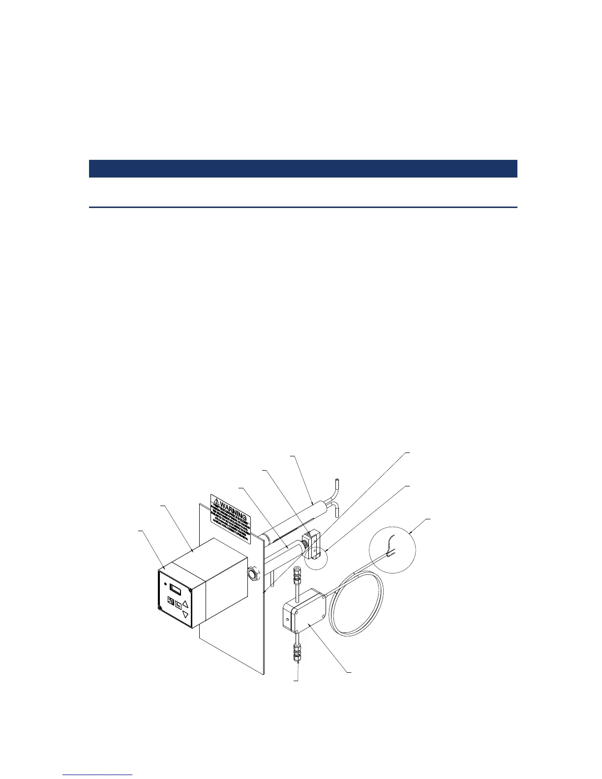
AutoVREL
control unit
AutoVREL
drive unit
Mounted after secondary cooling
Flow meter
TSV
TSV Switch
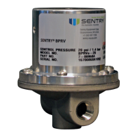
VREL control valve
Wire to ow meter