12 Sentry Equipment Corp
 NOTE
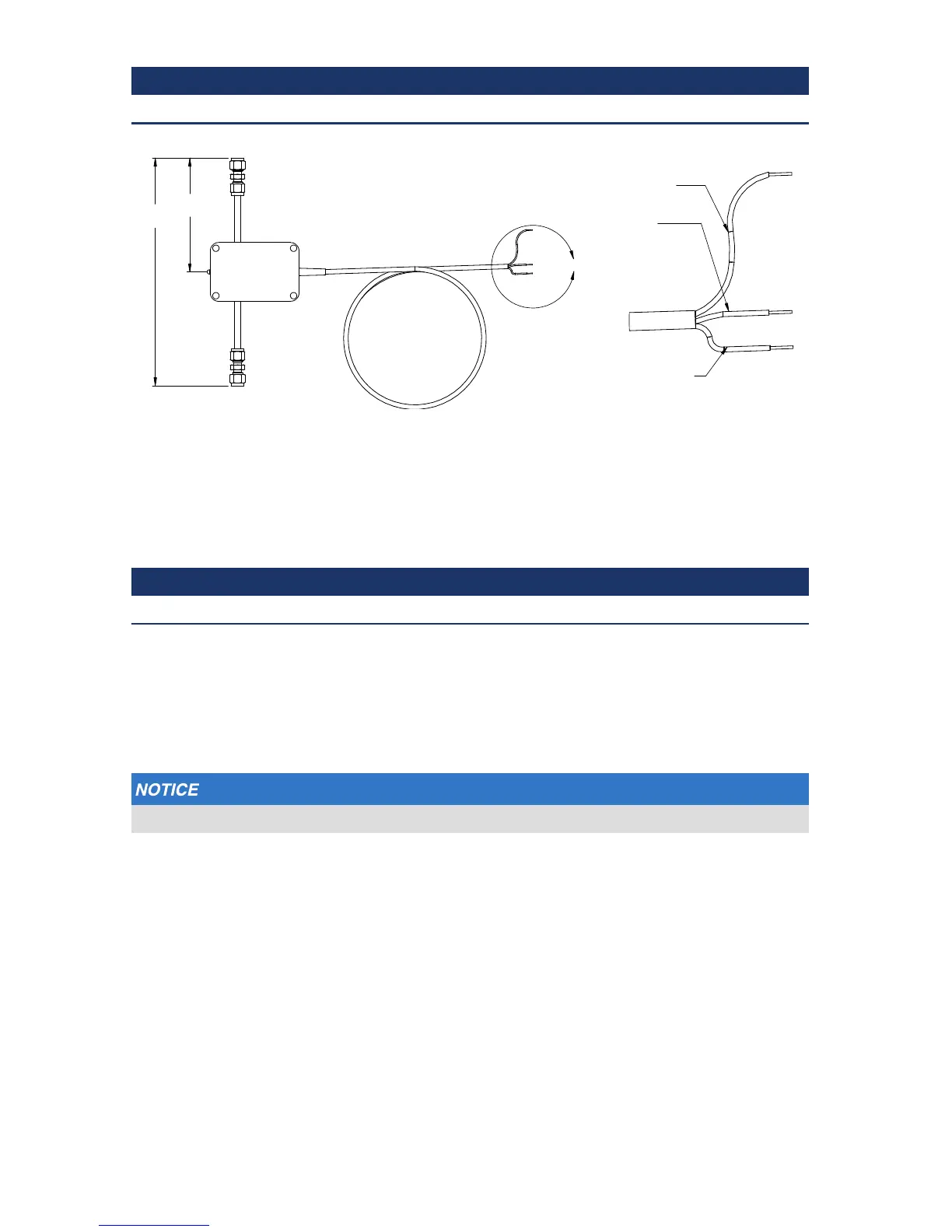
Default ow meter is pictured below; installation may dier for other ow meters.
13. Identify a location downstream of the VREL control valve after secondary cooling.
14. Once the tubing is cut, deburr all cut edges to prevent shavings from entering sample
lines.
15. Paying attention to the direction of ow listed on the ow meter (if listed), install the
ow meter.
 NOTE
Since each panel is unique, the complexity of ow meter installation will vary.
16. Install the provided cable gland in the 1-7/64-inch hole.
17. Once the ow meter is mounted, carefully route wires over to the back of the
AutoVREL ow controller and slide them through the cable gland and wire channel
until they are exposed to the front of the drive unit. This will be connected to the
controller.
Take care when installing connectors. They are delicate and can be damaged easily.
18. With the AutoVREL ow controller in one hand, carefully connect the wire harnesses
to the connectors on the back side of the controller. The TSV switch wiring should be
made to the Alarm Conn header pins 4 and 6.
E
9.90
4.95
NOTE:
Comes with 1/4” ttings
Detail E
Brown wire
(+24 VDC)
Blue wire
(GND)
Black wire
(4-20 mA sig)