SolaStat™-1-3 Installation Guide
Version 1.1 – April 2013 Page 6
INSTALLING THE SOLASTAT™ CONTROLLER, CONTINUED
Where to
mount the
SolaStat
TM
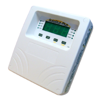
The SolaStat
TM
Controller should be mounted so that:
1. It is against a flat surface with sufficient strength to hold the enclosure
and any additional weight from the plugs, sockets and cables,
2. Power leads face down not sideways or up.
3. It is safe for users to inspect,
4. The display can be easily read and buttons accessed, and
5. Allowance is made for cable runs, location of power outlets and lengths
of wires.
Mounting the
SolaStat
TM
Note: In general, you should not need to open the Controller unit during
installation unless the installation is for a Hot Water Cylinder with two
elements.
Follow these steps:
1. Allow for the enclosure dropping 5 mm (1/5 inch) from screw centres
once mounted (keyhole mounting).
2. Place the drill guide template against wall, checking for level alignment.
Four screws are supplied: two chipboard screws and two combination
plasterboard/ wood screws.
All four mounting holes should be used with at least two firmly secured
into wood.
The outer plastic plasterboard anchors will self tap into plasterboard and
their inner metal screws fix into the centre of the plastic anchors.
3. Mark and drill/ screw as appropriate leaving the heads of the screws
above the surface by approximately 3 mm (1/8 inch).
4. Place the unit over the four screw heads. The unit should slide down
5mm into the ‘key’ slots and become secured to the wall. You will need to
adjust the screw height to obtain a secure fit.