For the following Detachable Input Cords with the self-locking
IEC C19 feature, follow Procedure A.
PTCORD-L1, PTCORD-L2, PTCORD-L3, PTCORD-L5, PTCORD-L6,
or PTCORD-L7.
For the following Detachable Input Cords, follow Procedure B.
PTCORD-1, PTCORD-2, PTCORD-3, PTCORD-4, PTCORD-5,
PTCORD-6, or PTCORD-7.
Procedure A
If the PRO2 was supplied with a Detachable Input Power Cord with a self-locking IEC C19, install it directly into
the C20 inlet.
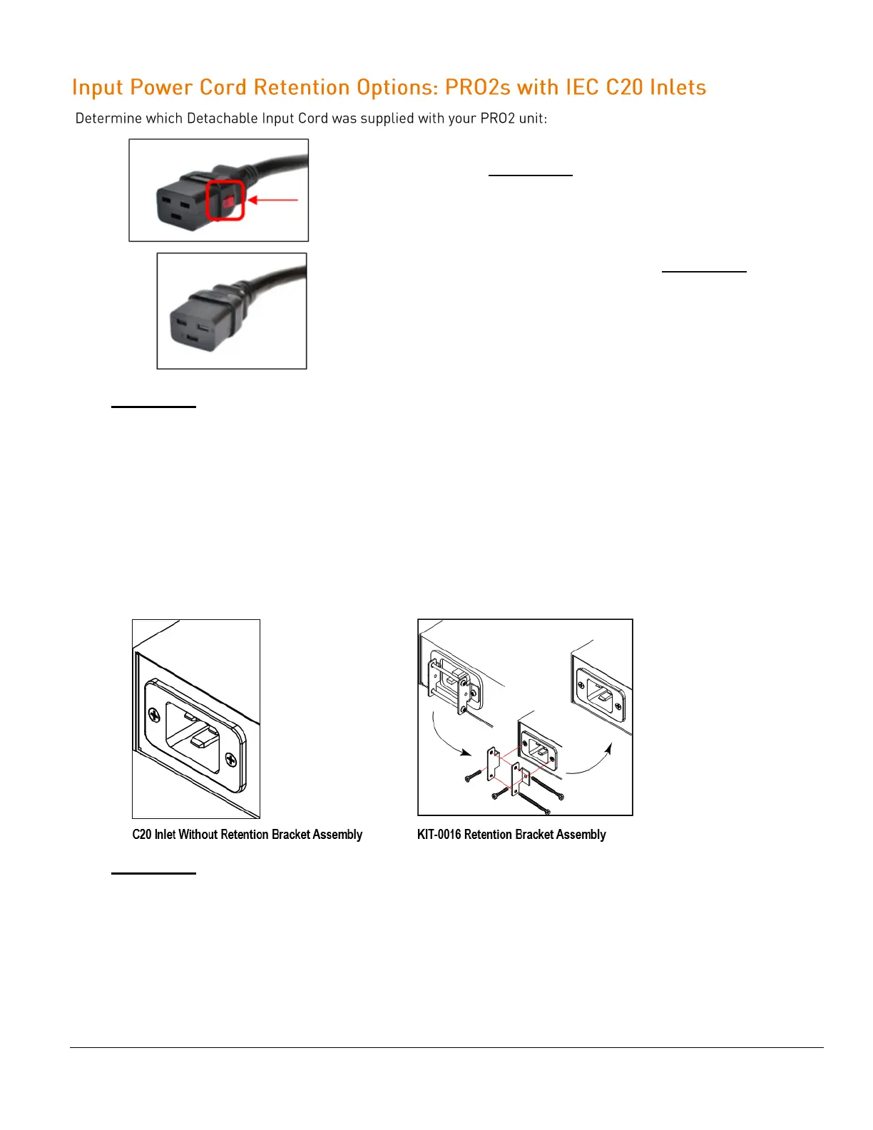
1. Verify the Retention Bracket Assembly (part number KIT-0016) is not installed.
a. If KIT-0016 is installed, remove the two screws attaching the bracket to the IEC 60320 C20 inlet to
the enclosure.
b. Remove the Retention Bracket Assembly.
c. Re-attach the two screws to the IEC C20 and securely tighten.
2. Push the C19 from the Detachable Input Cord firmly into the C20 inlet to ensure it is properly seated.
Procedure B
If the PRO2 was supplied with a Detachable Input Power Cord without the self-locking C19 feature, install with
the Retention Bracket Assembly (part number KIT-0016), followed by the power cord.
1. Remove the two screws attaching the IEC 60320 C20 inlet to the enclosure.
2. Assemble and attach the Retention Bracket to the enclosure as shown
3. Connect the power cord. Ensure the C19 is fully seated against the C20 inlet. (It may be necessary to
loosen some of the Retention Bracket Assembly screws to allow the C19 plug to be properly installed.)
4. Tighten the Retention Bracket Assembly to restrain the power cord.