20
Installation: Electrical connection
It is the responsibility of the installer to ensure the conformity towards national regulations of
all, not supplied cables.
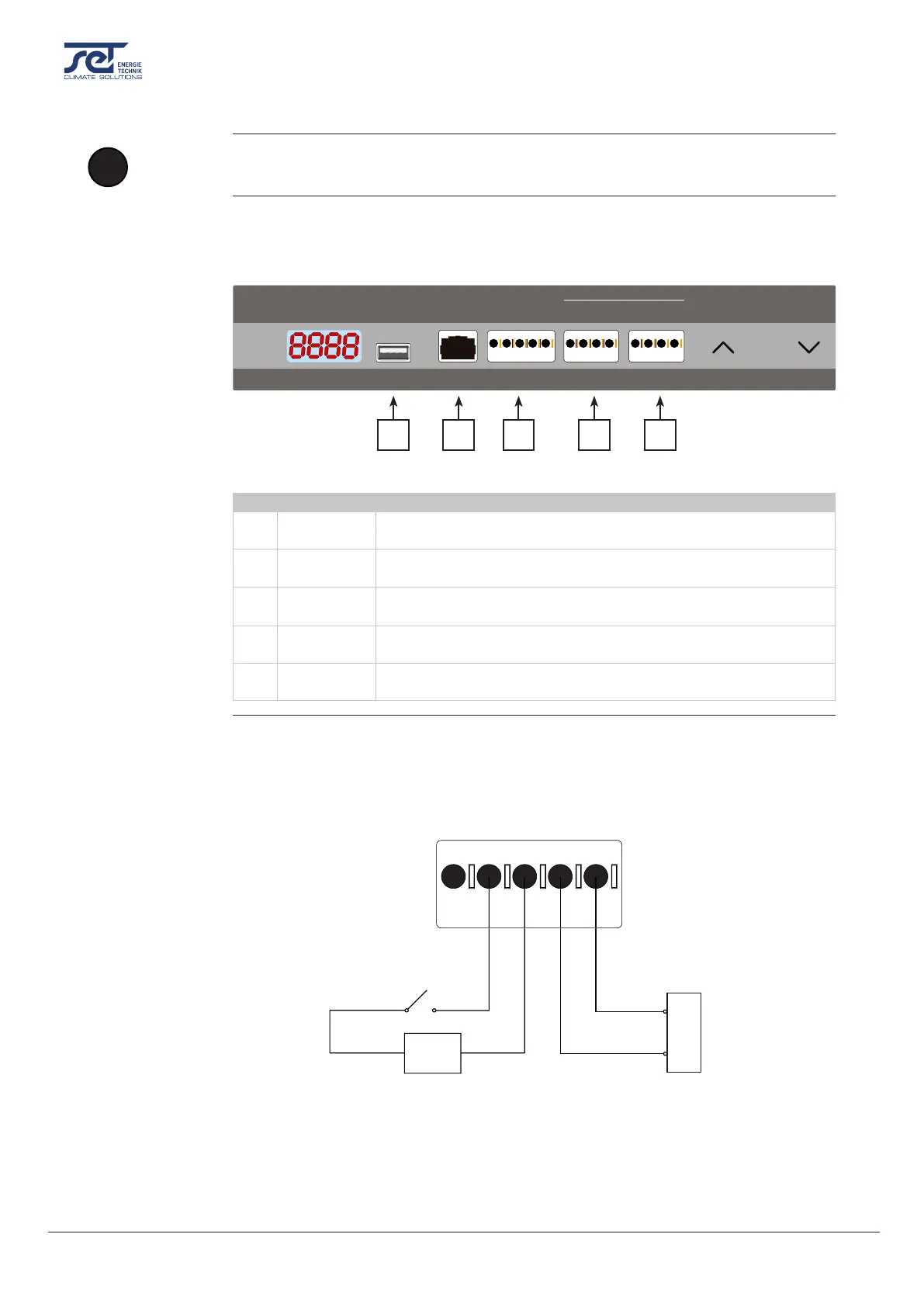
The interfaces and terminals on the control panel make it possible to communicate with the
dehumidier and connect accessory such as a RH/T sensor, an alarm and a heating coil. The
gure and table below describe the dierent functions of the interface.
+v
TH
TH
GND
GND
+
GND
+
RH
ON
ON
USB RS485
EXT RH/T ALARM 12V DC
RUN FAIL HEAT1 HEAT2
GND
+
GND
+
RH
ON
ON
OK
1 2 3 4 5
Fig. 6
Pos. Interface Description
1 USB USB is used for datalogging/ software update. See more information
in section “Software update and log les” on page 25.
2 Modbus RTU
(RS-485)
Connection via modbus. A list of data for the Modbus interface can be
downloaded on support.dantherm.com
3 External
RH/T sensor
Terminals for connecting an external humidity/ temperature sensor.
See wiring example in Fig. 7
4 Alarm An external alarm can reveal, if the dehumidier is operating normally
or has an error. See wiring example in Fig. 8
5 12 VDC
Heat control
Connection of LPHW (water) or electric heating helps controlling the
indoor temperature. Contact your SET dealer for more information.
There is an option for connecting an external RH/T sensor, which makes it possible to overrule
the internal sensors. In Fig. 7 there is an example on how it could be connected.
Fig. 7
*Switch in position: 0 = Internal sensors in use, 1 = External sensors in use
**Note, operational range is within 40-99% RH, if out of range the dehumidier will be in
stand by mode
!
NOTICE
Control panel
interfaces
External RH/T
sensor connection
(Optional)
External temperature sensor
(or resistor)
ON/OFF switch for
external sensors*
(Optional)
EXT RH/T
External humidity sensor
(or control unit)
V+
TH
TH
RH
GND
10kΩ NTC
0V = 0% RH
5V = 50% RH
0
1
GND
0-10V