Do you have a question about the SEW-Eurodrive MOVI-C UHX45A Series and is the answer not in the manual?
| Protection Class | IP20 |
|---|---|
| Series | UHX45A |
| Control Method | Vector control |
| Communication Interfaces | CANopen, PROFIBUS, EtherCAT |
| Ambient temperature | 0 °C |
| Relative humidity | 5% to 95% (non-condensing) |
| Control modes | Speed, torque, position |
| Encoder feedback | Incremental, absolute |
Provides context and scope of the documentation for users.
Details the presentation and meaning of safety notes and signal words.
Explains embedded safety notes integrated directly before dangerous actions.
Emphasizes reading documentation for fault-free operation and warranty fulfillment.
Covers exclusion of liability, other documentation, trademarks, and copyright notice.
General safety notes and outlines user responsibilities and qualifications.
Defines target personnel and intended use of the product.
Safety precautions for using the product in lifting applications.
Covers safety technology, transport, installation guidelines, and usage restrictions.
Details electrical installation, preventive measures, grounding, and bus system safety.
Covers manual scope, short designations, and additional documentation.
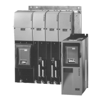
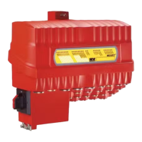
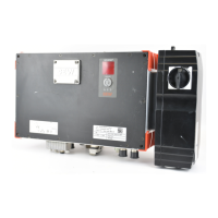
Introduces the controller, its capabilities, and different device variants.
Explains the information found on the device nameplate for various modules.
Explains the structure and meaning of type codes for controllers.
Illustrates and describes the various communication interfaces available on the controller.
Explains the role and contents of the SD memory card for controller operation.
Introduces MOVISUITE® software and its benefits for configuration and operation.
Lists standard accessories included and available for ordering.
Covers general mechanical installation, clearance, and mounting position requirements.
Details how to install the controller and modules within an axis system in a control cabinet.
Steps for mounting and removing the carrier plate for the compact controller.
Instructions for inserting and securing the compact controller.
Steps for mounting and removing the L-carrier for the master module.
Instructions for inserting and securing the master module.
Steps to remove the touch guard from the unit.
Instructions for installing busbars for DC 24 V supply and PE connection.
Steps for installing the touch guard and closing cover onto the last module.
Instructions for installing the top shield plate and controller removal.
Details electrical installation, protective separation, and bus cable shielding best practices.
Explains the function of various terminals on the MOVI-C® CONTROLLER.
Details the SD card slot, reset button, DIP switch, and fieldbus interface types.
Describes terminal connections for the L-carrier MDM90A.
Specifies power consumption and current for the compact controller's voltage supply.
Specifies power consumption and current for the master module's voltage supply.
Details how to connect an engineering PC to the controller via Ethernet.
Explains master connection and bus termination for EtherCAT®/SBusPLUS.
Covers CAN bus (in preparation) and connecting the controller as a fieldbus slave.
Details the integrated Ethernet switch, supported topologies, auto-crossing, and auto-negotiation.
Provides a comprehensive mapping of terminals, their connections, and functions.
Illustrates the location of status LEDs on the controller.
Lists and describes the meaning of various status LEDs (L/A, L1-L6, US1, BF).
Explains the meaning of LED L1 (firmware) and L2 (IEC program).
Details status LEDs L5, L6 (in preparation) and US1 (fieldbus operating state).
Explains status LEDs for bus faults and Ethernet link/activity.
Introduces Industrial Ethernet and TCP/IP parameters like MAC and IP addresses.
Explains network classes, subnet masks, and their role in IP addressing.
Covers standard gateway setup and automatic IP assignment via DHCP.
Explains device topology and tools for connecting the controller to PROFINET.
Details configuring EtherCAT®/SBusPLUS stations and establishing PC connection.
Step-by-step guide to set the IP address for the engineering PC.
Instructions on starting MOVISUITE® and performing a network scan.
Guide on applying scanned devices and displaying them in MOVISUITE® views.
Describes MOVISUITE® views and naming conventions for PROFINET and IEC61131 compliance.
Outlines the process for configuring fieldbus stations involving PLC, MOVISUITE®, and TIA Portal.
Explains the necessity of installing the GSDML file in TIA Portal.
Step-by-step guide to create a new project within TIA Portal.
Instructions on adding the PLC and configuring its device name in TIA Portal.
Details how to enter IP address parameters for the PLC in TIA Portal.
Describes adding the controller to TIA Portal, assigning names, and IP addresses.
Instructions for loading the GSDML file and adding the controller from the hardware catalog.
Assigning the device name to the MOVI-C® CONTROLLER within TIA Portal.
Details setting the IP address parameters for the MOVI-C® CONTROLLER in TIA Portal.
Assigning the PROFINET device name and adding process data words for the controller.
Steps to load the configured TIA Portal project to the PLC for activation.
Describes building the project and loading it to the PLC, including network search.
Procedure to assign the PROFINET device name if the status LED BF indicates an error.
Loading the MOVISUITE® project and device configuration via IEC Editor.
Configuring the fieldbus protocol (PROFINET IO) for the controller in MOVISUITE®.
Instructions to start a new project in the IEC Editor.
Connecting the IEC Editor project to the MOVI-C® CONTROLLER and scanning the network.
Building the IEC program and transferring it to the MOVI-C® CONTROLLER.
Starting the IEC program and verifying controller status and device tree.
Creating a boot project and overview of controlling stations during test run.
Instructions for creating a watch table to monitor process data exchange.
Establishing online connection and adding a watch table in TIA Portal.
Entering test values for process output data words in the watch table.
Starting variable monitoring and controlling active variables using icons.
Checking if process input values match sent test values in the IEC Editor.
Steps for replacing a controller, including SD card transfer and variable value storage.
Guidelines for proper disposal of the product and components according to regulations.
Lists compliance markings (CE, EAC, UL, RCM, RoHS, WEEE) and related directives.
Covers interference, ambient temperature, cooling, and environmental conditions.
Details electrical supply, memory, SD card slot, and interface specs for the compact controller.
Details electrical supply, connections, and PROFINET interface technical data.
Describes the functions of Ethernet, Engineering, and PROFINET ports.
Provides dimensional drawings and key measurements for the compact controller.
Provides dimensional drawings and key measurements for the master module.