Do you have a question about the SEW-Eurodrive MOVI-C UHX45A-N and is the answer not in the manual?
| Brand | SEW-Eurodrive |
|---|---|
| Model | MOVI-C UHX45A-N |
| Category | Controller |
| Language | English |
Details the purpose, audience, and accessibility of this manual.
Explains the grading and structure of safety notes and signal words used.
Details warranty claim fulfillment and reading the documentation beforehand.
SEW-EURODRIVE assumes no liability for injuries or damage from non-observance.
Recommends observing corresponding documentation for all further components.
States that product names are trademarks of their respective titleholders.
All rights reserved by SEW-EURODRIVE; unauthorized reproduction is prohibited.
General safety notes to prevent injury and damage to property.
Outlines user responsibilities for safe operation and compliance with regulations.
Defines the qualified personnel required for mechanical and electrotechnical work.
Specifies the intended application and installation requirements for the product.
Safety precautions for using the product in lifting applications.
States requirements for safety functions without a higher-level safety system.
Instructions for inspecting and transporting the device safely.
Guidelines for product installation, cooling, and protection from mechanical strain.
Prohibited applications and conditions for the device's operation.
Ensures covers are attached and protection devices comply with regulations.
Ensures the product is correctly attached to the ground connection.
Advises on adapting drive components and preventing unauthorized access.
Includes short designations, manual content overview, and additional documentation.
Lists the short designations used for products within the documentation.
Details the topics covered in the manual, including installation and interfaces.
Lists other manuals recommended for configuration and startup.
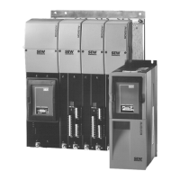
Introduces the MOVI-C® CONTROLLER as a motion controller for demanding automation tasks.
Lists the available MOVI-C® CONTROLLER device variants and their fieldbus interfaces.
Details the information found on the product's nameplate for compact and master modules.
Explains the structure of the type code for compact and master controllers.
Illustrates the various communication interfaces on the MOVI-C® CONTROLLER.
Describes the function and contents of the SD memory card for the MOVI-C® CONTROLLER.
Introduces MOVISUITE® as the operating platform for MOVI-C® components.
Highlights the benefits and features of using the MOVISUITE® software.
Lists standard accessories included and their part numbers for ordering.
Provides guidelines for mechanical installation, including clearance and mounting.
Specifies minimum clearance and correct mounting positions for cooling and access.
Illustrates control cabinet installation and axis system alignment for the controller.
Details the steps for mounting the MOVI-C® CONTROLLER onto a carrier plate.
Details the steps for removing the MOVI-C® CONTROLLER from a carrier plate.
Describes how to insert the MOVI-C® CONTROLLER onto retaining screws in the control cabinet.
Provides instructions for mounting the L-carrier to the MOVI-C® CONTROLLER.
Provides instructions for removing the L-carrier from the MOVI-C® CONTROLLER.
Describes inserting the master module onto retaining screws in the control cabinet.
Details the steps for removing the touch guard from the device.
Provides instructions for installing busbars for DC 24 V supply and PE connection.
Details the steps for installing the touch guard onto the module.
References procedures for removing compact and master modules.
Provides instructions for proper shielding and routing of bus cables to prevent interference.
Explains the function of each terminal on the MOVI-C® CONTROLLER.
Describes how to connect the DC 24 V power supply for compact and master modules.
Details connecting the engineering PC to the controller via Ethernet for communication.
Explains connecting the controller as an EtherCAT®/SBusPLUS master.
Notes that CAN system bus connection is in preparation.
Describes connecting the controller as a fieldbus slave via Ethernet.
Covers integrated Ethernet switch, auto-crossing, and auto-negotiation.
Provides a detailed table of terminal assignments and their functions.
Explains the status LEDs on the MOVI-C® CONTROLLER and their meanings.
Indicates firmware status during boot and operation.
Indicates the status of the IEC program.
Is reserved.
Displays the status of the system bus SBusPLUS.
In preparation.
In preparation.
Indicates the operating state of the fieldbus.
Indicates a bus error.
Indicates the status of the Ethernet connection.
Covers TCP/IP addressing, subnetworks, MAC and IP addresses.
Explains TCP/IP parameters: MAC address, IP address, subnet mask, gateway.
Defines the MAC address as a unique identifier for Ethernet devices.
Explains the IP address structure and representation as decimal numbers.
Determines network and node addresses based on the first IP address byte.
Explains how subnet masks divide network classes into finer sections.
Describes the standard gateway's role in connecting to other networks.
Explains automatic IP address assignment via a DHCP server.
Explains connecting the controller to a PROFINET network with device topology.
Explains configuring EtherCAT®/SBusPLUS stations using MOVISUITE®.
Details setting IP address parameters for PC-controller communication.
Describes the process of scanning the network for devices using MOVISUITE®.
Explains how to apply scanned devices and load device data into MOVISUITE®.
Covers configuring PLC as master and controller as slave using MOVISUITE® and TIA Portal.
Explains installing the GSDML file required for PROFINET IO configuration in TIA Portal.
Guides through creating a new project and adding a PLC in TIA Portal.
Details entering IP address parameters for the PLC within TIA Portal.
Describes adding the controller to TIA Portal, assigning name, IP, and process data.
Explains transferring TIA Portal project data to the PLC for activation.
Details loading the MOVISUITE® project and setting the fieldbus protocol.
Guides through successful communication testing between PLC and controller.
Explains creating watch tables for monitoring and controlling process data exchange.
Instructions for proper disposal of the product and its components according to regulations.
Lists the directives and guidelines the MOVI-C® CONTROLLER complies with.
Details general technical data, environmental conditions, and degree of protection.
Provides technical specifications for the MOVI-C® CONTROLLER advanced compact controller.
Provides technical specifications for the MOVI-C® CONTROLLER advanced master module.
Details the technical specifications for the PROFINET interface.
Describes the functions of Ethernet, Engineering, and PROFINET interfaces.
Lists the functions of the various Ethernet interfaces on the controller.
Details ports, functions, and authorization for the engineering interface.
Details ports, functions, and authorization for PROFINET communication.
Provides dimensional drawings for compact and master controller modules.
Shows the dimensions and layout of the compact MOVI-C® CONTROLLER.
Shows the dimensions and layout of the master module MOVI-C® CONTROLLER.