Do you have a question about the SEW-Eurodrive MOVIFIT FC and is the answer not in the manual?
| Type | MOVIFIT FC |
|---|---|
| Category | Controller |
| Control Method | V/f control, vector control |
| Storage Temperature Range | -40°C to +70°C |
| Relative Humidity | 5% to 95% (non-condensing) |
| Communication Interfaces | PROFINET, PROFIBUS, EtherNet/IP, Modbus TCP |
| Protection Class | IP65 |
| Dimensions | Varies depending on the specific model. Consult the product documentation for detailed dimensions. |
| Frequency Range | 0 Hz to 300 Hz |
| Cooling Method | Convection |
| Input Voltage | 3-phase 380-480V AC ±10% |
| Power Range | 0.37 kW to 200 kW |
Guidance on effectively using the manual for product understanding and operation.
Explanation of signal words and hazard symbols used in warning instructions for safety.
Introduction to safety notes concerning MOVIFIT® units and other SEW components.
Essential safety precautions regarding installation, operation, and handling of the MOVIFIT® unit.
Defines qualified electricians and trained personnel responsible for installation and operation.
Overview of the decentralized drive controller with integrated frequency inverter.
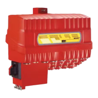
Description of the active electronics unit with communication interface, I/Os, and frequency inverter.
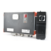
Description of the passive connection unit for terminals and cable connections.
Details on the optional design with enhanced IP protection and easy-to-clean housing.
Specific configuration for PROFINET communication using polymer optical fiber.
Information on EBOX unit identification and nameplate details for product specification.
Information on ABOX unit identification and nameplate details for product specification.
General guidelines and precautions for mechanical installation of the MOVIFIT® unit.
Approved positions and considerations for mounting the MOVIFIT® unit to ensure proper operation.
Detailed instructions and drilling templates for mounting the unit using a mounting rail.
Procedures for securing the unit, including screw types and quantities.
Steps for opening and closing the EBOX, including safety notices.
Specification for tightening blanking plugs included with the delivery.
Torque specifications for tightening EMC cable glands for proper installation.
Specific installation considerations for the Hygienicplus design to maintain IP69K protection.
General notes and precautions for electrical installation of the MOVIFIT® unit.
Guidelines for planning installations to minimize electromagnetic interference.
General instructions for connecting supply leads, residual current devices, and line contactors.
Information on calculating and providing the correct 24 V DC supply for unit components.
Specific requirements and notes for installations compliant with UL standards.
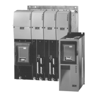
Guidelines for installing multiple MOVIFIT® units in a group drive configuration.
Visual example illustrating the general installation layout of MOVIFIT® FC units.
Description of the standard ABOX with terminals and cable bushings.
Overview of available variants for the standard ABOX based on fieldbus interface.
Diagram showing the location of various terminal blocks within the ABOX.
Detailed mapping of terminal numbers to functions for power and control connections.
Description of the hybrid ABOX, highlighting additional plug connectors compared to standard.
Overview of available variants for the hybrid ABOX based on fieldbus interface.
Diagram showing the location and type of plug connectors on the hybrid ABOX.
Description of the hybrid ABOX, highlighting additional plug connectors compared to standard.
Overview of available variants for the hybrid ABOX based on fieldbus interface.
Diagram showing the location and type of plug connectors on the hybrid ABOX.
Description of the hybrid ABOX with POF option L10, detailing plug connectors.
Overview of available variants for the hybrid ABOX with POF option L10.
Diagram showing the location and type of plug connectors for the hybrid ABOX with POF option.
Description of hybrid ABOXes with circular connectors for motor output and M12/fieldbus connectors.
Overview of available variants for hybrid ABOXes with circular connectors based on fieldbus interface.
Diagram showing plug connector locations for hybrid ABOXes with circular motor connectors.
Description of hybrid ABOXes with circular connectors for motor output and RJ45/Ethernet connectors.
Overview of available variants for hybrid ABOXes with circular motor connectors and RJ45.
Diagram showing plug connector locations for hybrid ABOXes with circular motor connectors and RJ45.
Information on available prefabricated connection cables for SEW components.
Details and wiring diagram for connecting the motor to the MOVIFIT® unit.
Description and assignment of digital input/output terminals based on function level and fieldbus.
Information on using Y adapters for connecting multiple sensors/actuators to M12 connectors.
Details on the Safe Torque Off (STO) connection for safety-related disconnection.
Wiring information for the PROFIBUS input connection.
Wiring information for the PROFIBUS output connection.
Wiring information for the DeviceNet™ interface connection.
Wiring information for Ethernet connections using M12, 4-pole, D-coded connectors.
Wiring details for the PROFINET POF interface connection using push-pull SCRJ.
Wiring details for the DC 24 V supply connection for the POF option L10.
Properties and installation details for the EI7 incremental encoder connection.
Example of power bus connection with a single 24 V circuit for supply.
Connection topology and setup for PROFIBUS communication using terminals.
Connection topology for PROFIBUS using M12 plug connectors.
Connection topology for Ethernet communication via RJ45 plug connectors.
Connection topology for DeviceNet™ communication using micro-style connectors.
Overview of available hybrid cables for connecting MOVIFIT® FC and motors.
Details on connecting hybrid cables, including terminal assignments and shield connections.
Important notes for correct motor phase and sensor connections to ensure proper direction and startup.
Guidelines for connecting brakes, including voltage requirements and digital output control.
Final steps after performing a wiring check, including reassembling the EBOX and sealing unused connections.
General safety and startup notes, emphasizing compliance with safety regulations.
Conditions and hardware/software required for successful startup of MOVIFIT®.
Explanation of DIP switch functions for device configuration and startup modes.
Overview of the MOVIFIT® FC startup process, including related documentation.
Steps for starting up MOVIFIT® units connected via fieldbus interfaces like PROFIBUS, PROFINET, DeviceNet™.
Procedures for starting up the MOVIFIT® frequency inverter using Easy or Expert modes.
Detailed steps for advanced startup and parameter configuration using MOVITOOLS® MotionStudio.
Explanation of general and bus-specific status LEDs for monitoring unit operation and diagnostics.
Interpretation of status LEDs for PROFIBUS communication, indicating bus status and errors.
Interpretation of status LEDs for DeviceNet™ communication, indicating bus status and errors.
Interpretation of status LEDs for PROFINET IO communication, indicating link, activity, and errors.
Interpretation of status LEDs for Modbus/TCP and EtherNet/IP™ communication, indicating module and network status.
Explanation of the "RUN PS" LED states indicating operating status, errors, and current limits.
Status indicators specific to optional modules like PROFIsafe S11 and S12 safety options.
Instructions for manual operation and parameterization using the DBG keypad via the diagnostic interface.
Overview of diagnostic tools available via MOVITOOLS® MotionStudio for troubleshooting.
Comprehensive list of error codes, possible causes, and recommended measures for troubleshooting.
Information on inspection and maintenance requirements for the MOVIFIT® unit, motor, and gear unit.
Procedures for safely shutting down and de-energizing the MOVIFIT® unit.
Guidelines for proper storage of the MOVIFIT® unit to prevent damage.
Specific recommendations for storing the unit for extended periods.
Important warning regarding capacitor aging and regeneration procedures.
Instructions for the proper disposal of the product components in accordance with regulations.
Information on compliance with various directives and standards like CE, EAC, UL, and C-Tick.
Detailed technical specifications for the unit operating at 400 V/50 Hz.
Detailed technical specifications for the unit operating at 460 V/60 Hz.
Electrical characteristics and current consumption for the unit's internal electronics and supply levels.
Specifications for the digital inputs, including number, type, and signal levels.
Specifications for the digital outputs DO00 to DO03, including type and current ratings.
Specifications for the binary output DB00, including output type and current ratings.
Information on various interfaces like SBus and RS485, including connection and transmission technologies.
Details on PROFIBUS, PROFINET IO, EtherNet/IP™, and Modbus/TCP interfaces, including protocol variants and addressing.
Mechanical and electrical properties of the hybrid cable type "A" used for motor connections.
Information on using the brake coil as a braking resistor in 4Q operation and regenerative load capacities.
Assignment and regenerative load capacity of internal braking resistors BW1T and BW2T.
Assignment and specifications for external braking resistors BW100, BW200, BW150, BW068.
Properties of sealing materials and surfaces for the Hygienicplus design, detailing chemical and temperature resistance.
List of optional metal cable glands and protective caps with their specifications and part numbers.
List of available accessories, including M12 plugs, pressure compensation fittings, and Ethernet adapters.
Visual representations of the unit's dimensions with standard and optional mounting rails.
Formal declaration confirming the product's conformity with relevant EC directives and harmonized standards.
Contact information for SEW-EURODRIVE offices and services within Germany.
Contact information for SEW-USOCOME offices and services within France.
Contact details for SEW-EURODRIVE INC. locations across various regions in the USA.