High-Power Stereo Class-D Audio Power Amplifier
SGM4703 with Adjustable Power Limit and Automatic Level Control
26
DECEMBER 2022
SG Micro Corp
www.sg-micro.com
APPLICATION INFORMATION (continued)
A high quality ceramic capacitor is needed for the ferrite
bead filter. A low ESR ceramic capacitor with good
temperature and voltage characteristics will be the best
choice. The capacitor value varies based on the ferrite
bead chosen and the actual speaker lead length. It is
crucial to place each ferrite bead filter tightly together
and individually close to VOPL/R and VONL/R pins
respectively.
Additional EMI improvements may be obtained by
adding snubber networks from each of the Class-D
outputs to ground. Suggested values for a simple RC
series snubber network are 10Ω in series with a 680pF
capacitor. Note that design of the RC snubber circuit is
specific to every application and must take into account
the parasitic reactance of the system board to reach
proper values of R and C. Evaluate and ensure that the
voltage spikes (overshoots and undershoots) at
VOPL/R and VONL/R on the actual system board are
within their absolute maximum ratings. Pay close
attention to the layout of the RC snubber circuit to be
tight and individually close to VOPL/R and VONL/R
pins, respectively.
LC Output Filter
For applications with nearby highly noise sensitive
circuits or long speaker wires, it may become
necessary to add an LC reconstruction filter for best
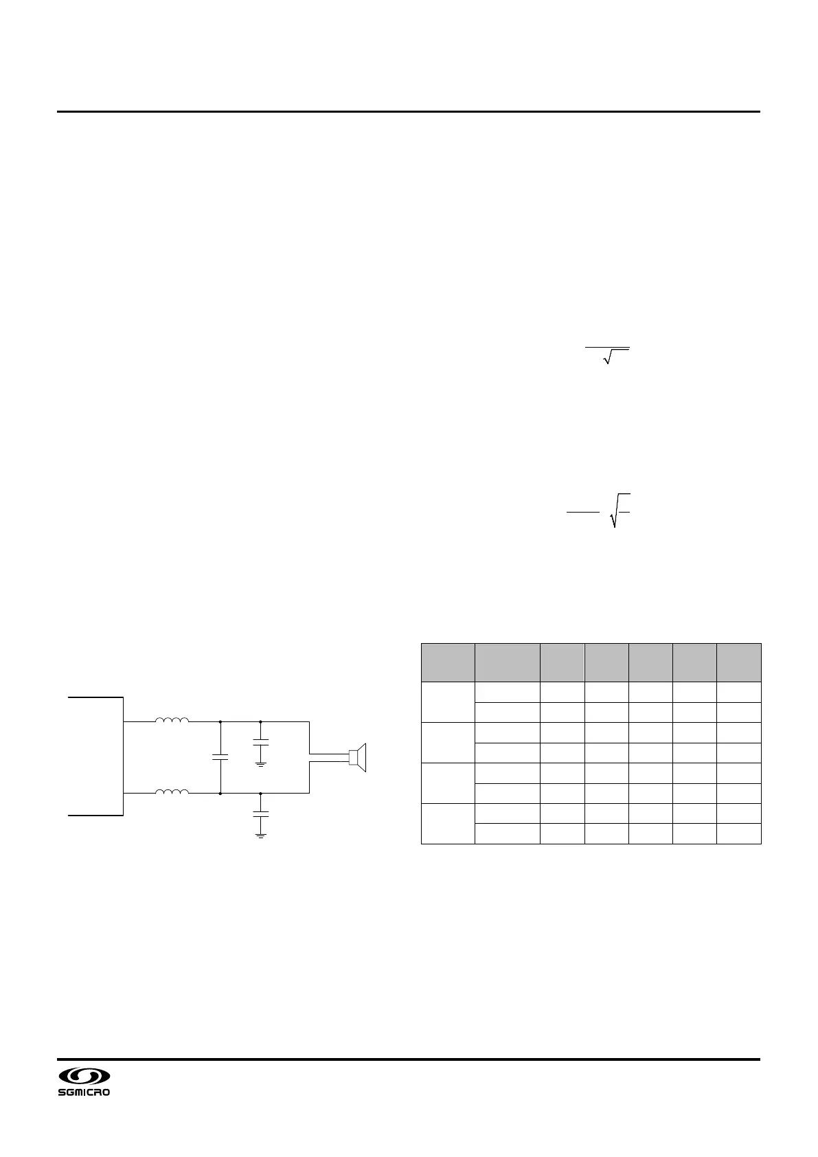
EMI reduction. A classic second-order low-pass filter,
as shown in Figure 15, can be used for the output filter.
LSL
SPEAKER
L
1
C
1
C
2
L
2
VOP
VON
C
3
Figure 15. LC Output Filter for EMI Reduction
In Figure 15, the corner frequency of the LC low-pass
filter, as given by Equation 3, must be designed to be
sufficiently high to allow for high-frequency components
of audio signals, yet be low enough to sufficiently
attenuate high-frequency components of the audio
outputs from VOPL/R and VONL/R. The corner
frequency of the filter is typically set about 50kHz. In
Equation 3, it is assumed that L = L
1
= L
2
, C
G
= C
2
= C
3
,
and C = 2 × C
1
+ C
G
.
(3)
The quality factor Q of the output filter is important.
Lower Q increases output noise and higher Q results in
passband peaking at frequencies near the corner
frequency. The quality factor of the filter is typically set
between 0.5 and 0.8. As shown in Equation 4, the
speak load, R
LOAD
, affects the quality factor of the filter.
(4)
Table 9 lists suggested component values of L
1
, L
2
, C
1
,
C
2
, and C
3
for the second-order Butterworth low-pass
filter with the speaker load at 2Ω, 3Ω, 4Ω, or 8Ω.
Table 9. Suggested Component Values of LC Output
Filter
Load
Modulation
Schemes
L
1
, L
2
(µH)
C
1
(µF)
C
2
, C
3
(µF)
f
C, LPF
(kHz)
Q
8
SSM 15 0.22 0.1 56 0.76
DSM
15 - 0.56 55 0.77
4
SSM 10 0.47 0.15 48 0.68
DSM
10 - 1.0 50 0.63
3
SSM 8.2 0.47 0.22 52 0.56
DSM
8.2 - 1.2 51 0.57
2
SSM 5.6 0.68 0.22 54 0.53
DSM
5.6 - 1.5 55 0.52
 Loading...