EasyManua.ls Logo

Sharp 20MR10 - User Manual

Sharp 20MR10
26 pages
Print Icon
To Next Page IconTo Next Page
Loading...
1
20MR10
COLOR TELEVISION
Chassis No. SN-010
In the interests of user-safety (Required by safety regulations in some countries) the set should be restored to its
original
condition
and only parts
identical
to those specified
should
be used.
ELECTRICAL SPECIFICA TIONS ......................................................................................................... 1
IMPORTANT SER VICE SAFETY PRECAUTION ................................................................................. 2
LOCATION OF USER'S CONTROL ..................................................................................................... 4
INSTALLATION AND SER VICE INSTRUCTIONS ................................................................................ 5
CHASSIS LAYOUT ............................................................................................................................. 11
BLOCK DIAGRAM .............................................................................................................................. 12
SCHEMATIC DIAGRAMS ................................................................................................................... 13
PRINTED WIRING BOARD ASSEMBLIES ........................................................................................ 20
REPLACEMENT PARTS LIST ............................................................................................................ 23
PACKING OF THE SET ...................................................................................................................... 29
Page
SHARP CORPORA TION
This document has been published to be used for after
sales service only.
The
contents
are
subject
to
change
without
notice.
CONTENTS
SER VICE MANUAL
POWER INPUT .................................................... AC 120 V, 60 Hz
POWER RATING ................................................................... 69 W
PICTURE SIZE ........................................... 1,194cm
2
(185sq inch)
CONVERGENCE ............................................................. Magnetic
SWEEP DEFLECTION .................................................... Magnetic
FOCUS ............................................... Hi-Bi-Potential Electrostatic
INTERMEDIATE FREQUENCIES
Picture IF Carrier Frequency..................................... 45.75 MHz
Sound IF Carrier Frequency...................................... 41.25 MHz
Color Sub-Carrier Frequency.................................... 42.17 MHz
(Nominal)
AUDIO POWER
OUTPUT RATING ..................................................... 1 W (RMS)
ELECTRICAL SPECIFICA TIONS
SPEAKER
SIZE ...................................................................... 8 cm (Round)
VOICE COIL IMPEDANCE ............................ 32 ohm at 400 Hz
ANTENNA INPUT IMPEDANCE
VHF/UHF ..................................................... 75 ohm Unbalanced
TUNING RANGES
VHF-Channels ............................................................... 2 thru 13
UHF-Channels ............................................................ 14 thru 69
CATV Channels ........................................................... 1 thru 125
(EIA, Channel Plan U.S.A.)
Specifications are subject to change without
prior notice.
MODEL
20MR10
S11O220MR10
P
O
W
E
R
V
O
L
C
H
V
I
D
E
O
A
U
D
I
O
I
N
M
E
N
U
Question and Answer IconNeed help?

Do you have a question about the Sharp 20MR10 and is the answer not in the manual?

Summary

Electrical Specifications

Important Service Safety Precautions

Servicing High Voltage and Picture Tube

Safety procedures for high voltage systems and picture tube handling.

X-Radiation and High Voltage Limits

Guidelines on X-radiation and high voltage measurement for safety.

Pre-Return Safety Checks and Notices

Before Returning the Receiver

Safety checks to perform before returning the unit to the user.

Installation and Service Instructions

Service Mode Operation and Adjustments

Service Adjustments

Picture Adjustments

Parts List: General and Initial Categories

Parts Replacement Guidelines

Information on safety characteristics of replacement parts.

Tuner, ICs, Transistors

Parts list for tuner, ICs, and transistors.

Parts List: Diodes, Capacitors, and Filters

Diodes, Coils, Capacitors

Parts list for diodes, coils, and capacitors.

Filters, Transformers, Controls

Parts list for filters, transformers, and controls.

Parts List: Resistors (Part 1)

Parts List: Resistors (Part 2)

Parts List: Resistors (Part 3) and Switches

Resistors (Continued)

Continues the parts list for resistors.

Switches and Miscellaneous Parts

Lists switches and miscellaneous parts.

Parts List: CRT Unit and Final Items

Overview

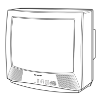
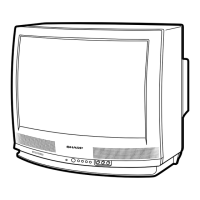
This document is a service manual for the Sharp 20MR10 Color Television, specifically for chassis model SN-010. It provides comprehensive information for service personnel, covering electrical specifications, safety precautions, user controls, installation and service instructions, chassis layout, block diagrams, schematic diagrams, printed wiring board assemblies, and a replacement parts list.

Function Description

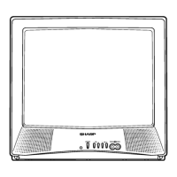
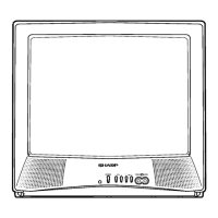
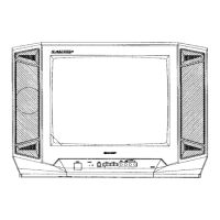
The Sharp 20MR10 is a color television designed for home entertainment. It receives and displays broadcast television signals, offering both VHF and UHF channel reception, as well as CATV channels. The television incorporates a high-voltage system for picture tube operation and an audio output for sound. It features user controls for power, volume, channel selection, and menu navigation, accessible both on the front panel and via an infrared remote control. The television also includes an external video input, allowing connection to other video sources.

Important Technical Specifications

Electrical Specifications:

  • Power Input: AC 120 V, 60 Hz
  • Power Rating: 69 W
  • Picture Size: 1,194 cm² (185 sq inch)
  • Convergence: Magnetic
  • Sweep Deflection: Magnetic
  • Focus: Hi-Bi-Potential Electrostatic

Intermediate Frequencies:

  • Picture IF Carrier Frequency: 45.75 MHz
  • Sound IF Carrier Frequency: 41.25 MHz
  • Color Sub-Carrier Frequency: 42.17 MHz (Nominal)

Audio Power:

  • Output Rating: 1 W (RMS)

Speaker:

  • Size: 8 cm (Round)
  • Voice Coil Impedance: 32 ohm at 400 Hz

Antenna Input Impedance:

  • VHF/UHF: 75 ohm Unbalanced

Tuning Ranges:

  • VHF-Channels: 2 thru 13
  • UHF-Channels: 14 thru 69
  • CATV Channels: 1 thru 125 (EIA, Channel Plan U.S.A.)

Circuit Protection:

  • The receiver is protected by a 4.0A fuse (F701), mounted on PWB-A.

High Voltage:

  • The high voltage should be approximately 26.0kV (at zero beam). This is a critical safety specification, and the manual emphasizes that high voltage is not adjustable but must be checked to verify it operates within safe design limitations.

Usage Features

User Controls (Front Panel):

  • Power: On/Off
  • Volume Up/Down: Increases/Decreases sound
  • Channel Up/Down: Selects next higher/lower channel; pressing both simultaneously accesses the MAIN MENU.
  • Video In/Audio In Terminals: For connecting external video sources.
  • Sensor Area: For remote control reception.

User Controls (Remote Control - G1339SB):

  • Power: On/Off
  • Input: Switches between external video input mode and TV mode.
  • Remote Keypad (0-100): Accesses any channel directly.
  • Flashback: Returns to the previous channel.
  • Volume Up/Down: Increases/Decreases sound; in menu mode, changes or selects TV adjustments.
  • Mute: Mutes/Restores sound; displays "CLOSED CAPTION" when sound is muted.
  • Menu: Accesses/Exits MAIN MENU.
  • Display: Displays receiving channel for four seconds; removes display; temporarily displays receiving channel in Closed Caption mode.

Maintenance Features

Important Service Safety Precaution:

  • Service work should only be performed by qualified technicians familiar with safety checks and servicing guidelines.
  • No circuit modification should be attempted for continued safety.
  • Always disconnect AC power before servicing.
  • Semiconductor heat sinks are potential shock hazards when the chassis is operating.
  • The chassis has two separated ground systems (non-isolated/hot and isolated); an isolation transformer is recommended when servicing.
  • Fuse Replacement: For continued protection against fire risk, replace only with the same type 4A-125V fuse.

Servicing of High Voltage System and Picture Tube:

  • Before servicing the high voltage system, static charge must be removed by connecting a 10k ohm resistor in series with an insulated wire between the picture tube ground and the anode lead (with AC line cord disconnected).
  • The picture tube employs integral implosion protection.
  • Replace the picture tube with the same type number for continued safety.
  • Do not lift the picture tube by the neck.
  • Handle the picture tube only with shatterproof goggles and after completely discharging the high voltage anode.

X-Radiation and High Voltage Limits:

  • Service personnel must be aware of X-radiation procedures. The picture tube is the only potential source of X-ray; it does not emit measurable X-ray radiation if high voltage is as specified.
  • High voltage must be kept below the maximum level specified.
  • An accurate high voltage meter, checked periodically, is essential.
  • High voltage should always be kept at the rated value; operation at higher voltages can cause failure and excessive radiation.
  • The high voltage regulator must operate properly to prevent X-radiation problems.
  • Brightness should be tested while monitoring high voltage to ensure it does not exceed the specified value and regulates correctly.
  • Do not use a picture tube other than specified or make unrecommended circuit modifications to the high voltage circuitry.
  • Avoid unnecessary proximity to the receiver when troubleshooting with excessive high voltage.
  • Do not operate the receiver longer than necessary to locate the cause of excessive voltage.

Circuit Protection Test (X-Radiation Protection):

  • After servicing the horizontal deflection, high voltage, or B+ systems, the X-Radiation protection circuit must be tested.
  • This involves applying 120V AC (using a variac), allowing warm-up, adjusting controls for normal picture/sound, receiving a good local channel, and checking voltage at TP653 (21.4 ±1.5V).
  • External 27.2V DC is applied at TP653 (TV off), then the protector is reset by unplugging the AC cord and shorting TP651 and TP652. Normal picture appearance confirms proper operation. If the horizontal oscillator does not stop, the circuit must be repaired.

High Voltage Check:

  • Connect an accurate high voltage meter between ground and the picture tube anode.
  • Operate the receiver for at least 15 minutes at 120V AC line voltage with a strong air signal or tuned test signal.
  • Enter service mode, select "S03" and Bus data "01" (Y-mute on).
  • The voltage should be approximately 26.0kV (at zero beam).
  • If the reading is incorrect, check for malfunctioning components. After the test, set Y-mute off.

Service Mode Adjustments:

  • To enter service mode: Press Vol-up and Ch-up buttons simultaneously while plugging the AC cord into a wall socket.
  • To exit service mode: Press the power button.
  • The service mode offers three adjustment categories: DEF (Deflection), SIGNAL, and FIX VALUE.
  • Adjustments include: RF AGC, Video Level, Screen, White Balance, Sub-Picture, Sub-Tint, Sub-Color, Sub-Brightness, Vertical-Size, V-Linearity, V-S Correction, Horizontal Position, Vertical-Phase, and Caption Position.
  • Data numbers for adjustments are selected and adjusted using VOL UP/DOWN and CH UP/DOWN buttons.
  • Holding Vol-up/Ch-down for over 2 seconds in service mode writes initial values into IC2102 (IC2101).
  • Specific adjustments are required when replacing certain ICs (IC2001, IC201, IC2102/IC2101) or the CRT.

Safety Notice:

  • Many electrical and mechanical parts have special safety-related characteristics.
  • Replacement parts must be identical to those used in the original circuit, identified by "!" and shaded areas in the Parts Lists and Schematic Diagrams.
  • Using substitute parts without the same safety characteristics may create shock, fire, X-radiation, or other hazards.

Packing of the Set:

  • Detailed instructions for packing the television, including the use of polyethylene bags, wrapping paper, buffer material, and specific stapling instructions for the packing case, are provided to ensure safe transport.
  • The manual also lists packing parts (e.g., packing case, wrapping paper, buffer material, polyethylene bag) and cabinet parts (e.g., front cabinet assembly, R/C cover, SHARP badge, buttons, rear cabinet).

Sharp 20MR10 Specifications

General IconGeneral
BrandSharp
Model20MR10
CategoryTV
LanguageEnglish

Related product manuals