NO
ADJUSTMENT POINT
ADJUSTMENT CONDITION / PROCEDURE WAVEFORM OR OTHERS
1 SUB COLOUR (1) Receive the "PAL Color Bar" signal. Cy G B
(I2C BUS CONTROL) (2) Press R/C to set Picture Normal condition.
(to be done after
sub-picture, sub-tint adj)
(3) Connect the oscilloscope to
R-Amp Transistor Base
(JUMPER 401)
Range :
100mV/Div
(AC) (Using 10:1 Probe)
Sweep Time :
10µsec/Div
75% W Y 100% W Mg R
(4) Using the R/C call
V05
in SERVICE mode. Adjust
V05
bus data, so that the 75% White & Red portions of PAL Color Bar be
at the
same level
shown as Fig 1-1. Fig. 1-1
(5) Clear the SERVICE mode.
NTSC CHROMA ADJUSTMENT
NO
ADJUSTMENT POINT
ADJUSTMENT CONDITION / PROCEDURE WAVEFORM OR OTHERS
1 SUB-TINT (1) Receive the "NTSC 3.58 Color Bar" signal thru AV in.
straight line slope
(I2C BUS CONTROL)
(2) Connect the oscilloscope to B-AMP Transistor Base
(JUMPER 410)
.
(3) In Service mode, go to
V07, then
press
R/C Y-mute (Hex E4)
or
FLASHBACK
key.
(4) Call the "
V07
" data in service mode. Adjust the "
V07
" bus
data to obtain the waveform shown as Figure 1-1.
(5) Disable
Y-Mute
by pressing key
(Hex E4
) or
FLASHBACK
, then clear the
SERVICE mode. *NOTE : Please make sure waveform is adjusted until getting
good step slope which is can be a straight line slope at the
NO
ADJUSTMENT POINT
ADJUSTMENT CONDITION / PROCEDURE WAVEFORM OR OTHERS
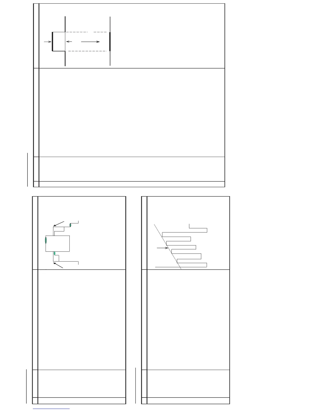
1 SECAM 1) Receive "SECAM ALL WHITE" signal.
BLACK LEVEL
R-Y / B-Y
2) In the service mode, select service data
V14
.
Fig 2(a)
3) Connect oscilloscope to
TP 801
.
Offset
20mV/Div
(AC) (use 10:1 probe)
4) Adjust the
V14
so that the offset of R-Y to minimum, shown in
Fig 2(b)
, it means
adjust the offset of between No signal line and Signal line to minimum
Fig 2(b)
Offset
5) In the service mode, select service data
V15
.
6) Connect oscilloscope to
TP 801
.
20mV/Div
(AC) (use 10:1 probe)
7) Adjust the
V15
so that the offset of B-Y to minimum, shown in
Fig 2(b)
, it means
adjust the offset of between No signal line and Signal line to minimum