21S-FX10L
5 – 6
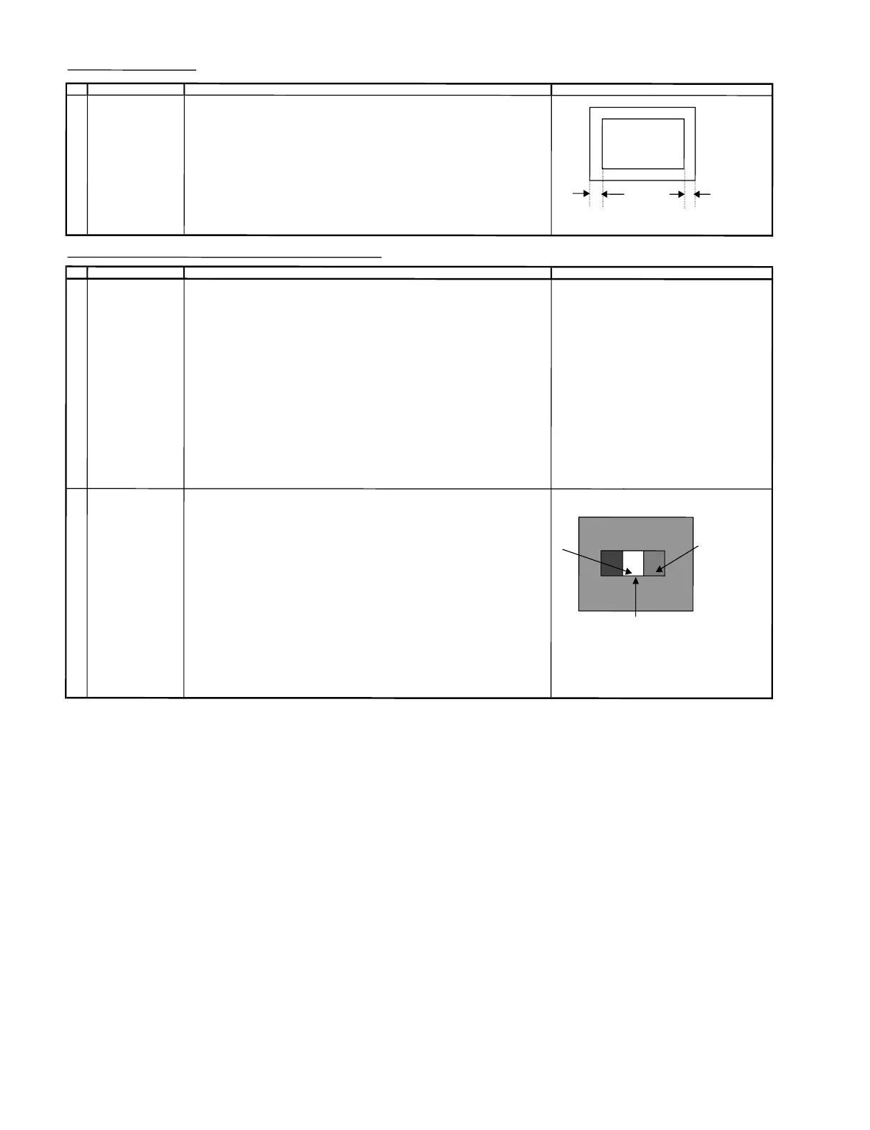
CLOSED CAP
TION ADJUSTMEN
T
NO
ADJUSTMENT POINT
ADJUSTMENT CONDIT
ION / PROCEDURE
WAVE
FORM OR OTHERS
1
CLOSED CAPTION (1) Recei
ve US4 CH LION HEAD Signal (NT
SC 60 H
z)
SET UP (2) Go to service mode, choose service data V22
.
(3) Adjust the V22 bus data tohaveab
a
l
ance position tos
pec ofA=B
(4) After the left and right s
y
mmetrical t
hen
V
22 data reduce 5 step
AB
SCREEN, WHI
TE BALANCE, SUB
-BRIGHTN
ESS &
SUB-C
ONTRAST ADJUSTMENT(1)
NO
A
DJUSTMENT POINT
A
DJUSTMENT
CON
DITION / PROCEDURE WAVE
FORM OR OTHERS
1
SCR
EEN
(1) Set t
he se
rvice d
ata before adjus
t CRT cutoff as fol
lows:
N
OTE:
ADJUSTMENT
a) V01 : 127
Servic
edata
R/C key (Hex)
(I2C
BUS CONTROL)
b) V04
:127 R-cutoff up A9
c) V15
:127 R-cutoff down69
d) V16 : 127 G-cutoff upE9
e) V17:127 G
-cutoff down 19
f) V18 : 64
B
-cuto
ff up 99
g) V19 : 64 B-cutoff down
5
9
(2) Receive the window pattern or US4 CH LION
H
EA
DSignal (NT
SC 60
Hz)
(3) Go to service mode, get in Y-mute b
y
R/
C and set V23 to "1"
(4)Adjustthe Screen so that cut-off line appear in low bright, then judge that whethe
r
the cut-off data appear in Red or Green or Bluecolor, in this conditionbetwe
en
V15 = R-CUTOFF,
V16=G-CUTOFF & V17= B-CUTOFF, fix the data of the
colorappear in cut-off line and adj the
other two cut-off line s
othatcu
t-off l
ine color become white
.
(5)T
u
rn the s
creen VR of FBT so that cut-off linej
ust
disappea
r and use R/C t
oset
V
23 to "0".
Next dis
ab
le the Y-Mute so that the picture appear in n
ormal mode
2
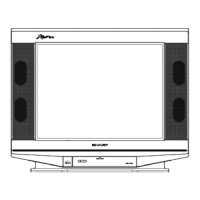
WHITE BALANCE AD
J (1)WHITE (HIGH BEAM)
(to
be done after s
creen First use Minolta Color Analyzer CA100, let the gun pointat Dark White position
adj) (as d
rawing attach), Adj
V
04 until LUMINANCE Y become 5 cd/m2,thenlet thegun
(I2C BUS CONTROL)
p
oint at White position ( as drawing attac
h
), Adj V01 until LUMINANCE Y
(CH 23 50IRE become: 1
50 cd/m2. White Dark
WINDOW PATT
ERN) Adj the
V18(R DRIVE) , V19(B DRI
VE) until the axis of color temperature become
White
10700° X : 0.278 , Y : 0.280
(2) DARK WHITE (LOW BEAM)
Let t
he gun point at Dark White position, ifthe color temperature data shift away from
the data adjus
t
ed in
Item 1
Screen adj
ustment,adjust V15,
V
16,
V
1
7.
Please fix t
h
e first colour appear
s in Screen a
dj item
step (4) is fi
xed,
ad
jtheother twos
o
t
hat to
o
btai
nthe similar axis as
ab
o
v
e
*
Not
e:
Use RF CH
2
3
5
0
IRE window pattern
*
* Repeat step 1 & 2 to get a re
gulated position
5
0%
W
HITE