In the interests of user-safety (Required by safety regulations in some countries) the set should be restored to its
original condition and only parts identical to those specified should be used.
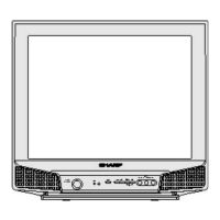
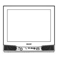
COLOR TELEVISION
Chassis No. GA-4M
MODEL
Page
ELECTRICAL SPECIFICATIONS .................................................................................................. 1
IMPORTANT SERVICE SAFETY PRECAUTION ......................................................................... 2
LOCATION OF USER'S CONTROL .............................................................................................. 4
INSTALLATION AND SERVICE INSTRUCTIONS ........................................................................ 5
SERVICE MODE ...........................................................................................................................
6
ADJUSTMENT METHOD ..............................................................................................................
CHASSIS LAYOUT ....................................................................................................................... 26
BLOCK DIAGRAM
........................................................................................................................
27
SCHEMATIC DIAGRAMS ...........................................................................................................
PRINTED WIRING BOARD ASSEMBLIES ................................................................................... 36
REPLACEMENT PARTS LIST ...................................................................................................... 40
PACKING OF THE SET ................................................................................................................ 47
CONTENTS
POWER INPUT .......................... 110-230 V AC,60 Hz
POWER RATING .............................................. 85 W
PICTURE SIZE
...................... 1,239 cm
2
(192sq inch)
CONVERGENCE ......................................... Magnetic
SWEEP DEFLECTION ............................... Magnetic
FOCUS ............................ Hi-Bi-Potential Electrostatic
INTERMEDIATE FREQUENCIES
Picture IF Carrier Frequency ................... 45.75 MHz
Sound IF Carrier Frequency .................... 41.25 MHz
Color Sub-Carrier Frequency .................. 42.17 MHz
(Nominal)
AUDIO POWER OUTPUT RATING ...............
3 W + 3 W
SPEAKER
SIZE .......................................................
9 cm x 5 cm
VOICE COIL IMPEDANCE
...............
16 ohm at 400 Hz
ANTENNA INPUT IMPEDANCE
VHF/UHF
..................................75 ohm Unbalanced
TUNING RANGES
VHF-Channels .......................................... 2 thru 13
UHF-Channels ........................................ 14 thru 69
CATV Channels ...................................... 1 thru 125
ELECTRICAL SPECIFICATIONS
TVSM056-21V-FR95S(SL)
Specifications are subject to change without
prior notice.
SERVICE MANUAL
SHARP (PHILS.) CORPORATION
Km. 23 West Service Road, South Super Highway Alabang, City of Muntinlupa
12
32
21V-FR95S (SL)
21V-FR95S (SL)