10
29A-SX1
29A-SX5
29A-SX8
SX-68JF200
10
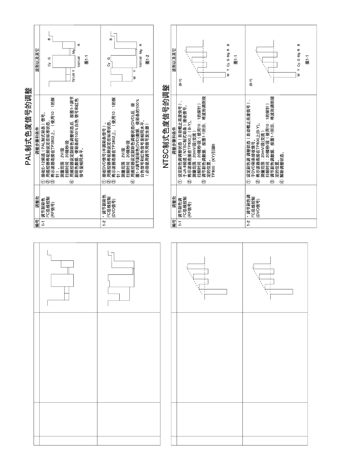
PAL CHROMA ADJUSTMENT
NO. Adjustment part Adjusting procedure and conditions Waveform and others
1-1
SUB-COLOUR
I
2
C bus adjust-
ment (RF signal)
1 E-12CH(PAL colour bar) is received.
2 Make the image normal with the remote con-
troller.
3 Connect the oscilloscope to TP3802. (10:1
probe is used.)
Range: 2V/Div.
Sweep time : 20µsec/Div.
4 Set the sub colour adjustment mode with the
remote controller, and vary the sub colour data
to make 100%W of the colour bar and RED at
the same level for adjustment shown in Fig. 1-
1.
Fig. 1-1
NO. Adjustment part Adjusting procedure and conditions Waveform and others
1-1
SUB-TINT
I
2
C bus adjust-
ment (RF signal)
1 Select the sub-tint adjustment mode (automatic
Y cut) to receive JA-8CH(NTSC colour bar).
2 Connect the oscilloscope to TP800 (B-Y).
Range : 20mV/Div. (AC)
Sweep time: 20µsec/Div. (10:1 probe is used.)
3 Vary the sub tint data to adjust the waveform to
be gained as shown in Fig. 1-1.
TP800.............(KY) 6 pin
1-2 * SUB-TINT
I
2
C bus adjust-
ment (DVD
signal)
1 Select the sub-tint adjustment mode (automatic
Y cut) to receive the DVD colour bar signal.
2 Connect the oscilloscope to TP800(B-Y).
Range : 20mV/Div. (AC)
Sweep time: 20µsec/Div. (10:1 probe is used.).
3 Vary the sub tint data to adjust the waveform to
be gained as shown in Fig. 1-1.
4 Release the adjustment mode.
NTSC CHROMA ADJUSTMENT
1-2 * SUB-COLOUR
I
2
C bus adjust-
ment (DVD
signal)
1 DVD signal is received. (Half colour bar signal)
2 Make the image normal with the remote con-
troller.
3 Connect the oscilloscope to TP3802. (10:1
probe is used.)
Range : 2V/Div.
Sweep time: 20µsec/Div.
4 Set the sub colour adjustment mode (DVD) with
the remote controller, and vary the sub colour
(DVD) data to make 100%W of the colour bar
and RED at the same level for adjustment
shown in Fig. 1-2. (* It is being examined.)
Fig. 1-2