SX-68JF200
14
SUB CONT SUB-BRIGHT ADJUSTMENT
NO. Adjustment part Adjusting procedure and conditions Waveform and others
3
MAX BEEM
R1633
1 Receive E-5CH (Monoscope pattern) with
standard mode.
2 Make the image normal with the remote con-
troller.
3 Connect the beam ammeter between TP1601
and TP1602.
Ammeter full scale 3mA range
TP1602 is connected at the - side of the
ammeter.
TP1601 is connected at the + side of the
ammeter.
4 Adjust the beam current to 1.7mA ± 50µA with
R1633 (sub-contrast VR).
Note : Apply the adjustment after aging with the
beam current 1,500 ± 50µA or more for
30 minutes or more.
(On the white or green monocolour
screen)
1 Select the DVD mode.
2 Receive the signal of the DVD signal genera-
tor. (Component signal)
(Window pattern)
3 Make the image normal with the remote con-
troller.
4 Select the SUB-CONTRAST adjustment mode
(DVD) with the remote controller, and adjust
50% white to 110 ± 3cd.
SUB-BRIGHT
I
2
C bus adjust-
ment (RF signal)
SUB-CONTRAST
I
2
C bus adjust-
ment (RF signal)
SUB-CONTRAST
I
2
C bus adjust-
ment (DVD
signal)
SUB-BRIGHT
I
2
C bus adjust-
ment (DVD
signal)
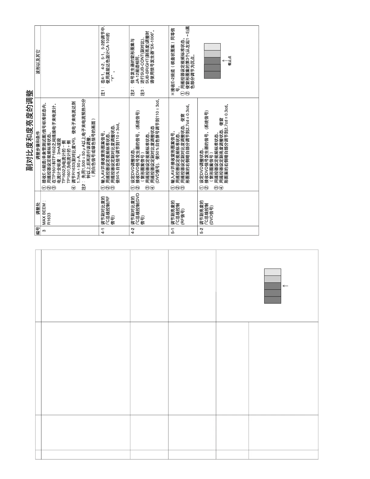
* When E-2CH (Crosshatch pattern) or
equivalent signal is received.
1 Make the image normal with the
remote controller.
2 Adjust the 3rd (1 thru 5 from the
left) black of the window pattern to
sink.
1 Receive the window pattern with AV input.
2 Make the image normal with the remote con-
troller.
3 Select the sub-bright adjustment mode with the
remote controller, and adjust the right dark white
area of the window pattern to 2.7cd ± 0.3cd.
1 Select the DVD mode.
2 Receive the signal of the DVD signal genera-
tor. (Component signal) (Window pattern)
3 Make the image normal with the remote con-
troller.
4 Select the sub-bright adjustment mode (DVD),
and adjust the right dark white area of the win-
dow pattern to 2.7cd ± 0.3cd of the window
pattern.
1 Receive the window pattern with AV input.
2 Make the image normal with the remote con-
troller.
3 Select the SUB-CONTRAST adjustment mode
with the remote controller, and adjust 50% white
to 110 ± 3cd.
Note 1 : Use “Y” of Minolta colour
analyzer CA-100 in adjust-
ment 4-1, 4-2, 5-1, 5-2.
4-1
4-2
5-1
5-2
Note 2 : Window pattern of signal
generator is same ad JA-
12CH.
Note 3 : Use the signal generator
"SX-1006" for SUB-CONT.,
SUB-BRIGHT adjustment.