SX-68JF200
15
PURITY ADJUSTMENT
NO. Adjustment part Adjusting procedure and conditions Waveform and others
1
Purity adjust-
ment
1 Select the green monocolour screen with the
remote controller, and set the beam current of
1.5mA with the contrast control.
2 Sufficiently degauss CRT with the degusing coil.
Note : For the adjustable magnetic field, refer to
the job instruction sheet.
The adjustable magnetic field is as shown
page 9.
3 The purity magnet must be previously set at
the 0 magnetic field, and the convergence must
be adjusted to be rough.
With P-MG, adjust it to the center - rank A.
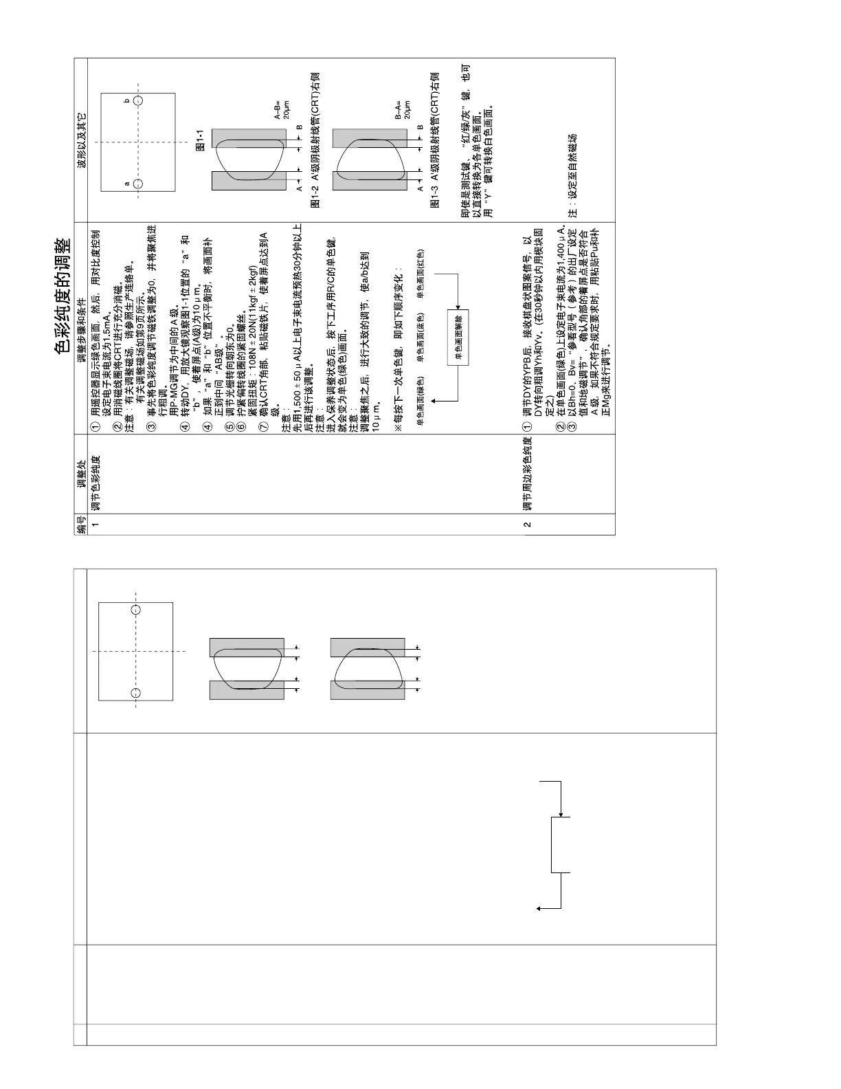
4 Observing the points a and b of Fig. 1-1 with
the microscope, move DY fore and aft to set
the landing at the point (Rank A) of 10µm.
4 If the a/b balance is poor, compensate it to the
center “Rank AB”.
5 Align it to zero, keeping the raster rotation in
the east direction.
6 Tighten the deflection coil fastening screws.
Tightening torque: 108N ± 20N (11kgf ± 2kgf)
7 Checking the CRT corner area, bond the mag-
netic sheet to set the landing at Rank A for com-
pensation.
Note : Apply the adjustment after aging with the
beam current 1,500 ± 50µA or more for 30
minutes or more.
Note : Select the service mode, and press the
monocolour key of R/C for process, and the
monocolour screen (green) will be selected.
Note : After adjusting the convergence, perform
rough adjustment so that a/b gets to 10µm.
* Every push of the monocolour key changes the
screen as follows.
Fig. 1-1
Fig. 1-2 Rank A’ CRT RIGHT
Fig. 1-3 Rank A’ CRT LEFT
Even with TEXT key or “R.G.Cy” key,
it can be directly switched to each
monocolour screen.
With "Y" key, it can be switched
WHITE screen.
Peripheral purity
adjustment
2
1 After YPB adjustment of DY, receive the cross-
hatch, and coarsely adjust Yh and Yv by swing-
ing DY. (Fix it with the wedge within 30 sec-
onds.)
2 In the monocolour screen (green), set the beam
current at 1,400µA.
3 In Bh=0 and Bv= “Refer to the factory setting
and geomagnetic adjustment by model (ref.)”,
verify that the landing in the corner area is prac-
tically at the rank A. If it is deviated, bond the
Pu compensation Mg for adjustment.
Note : Set to natural magnetic field.