SX-68JF200
20
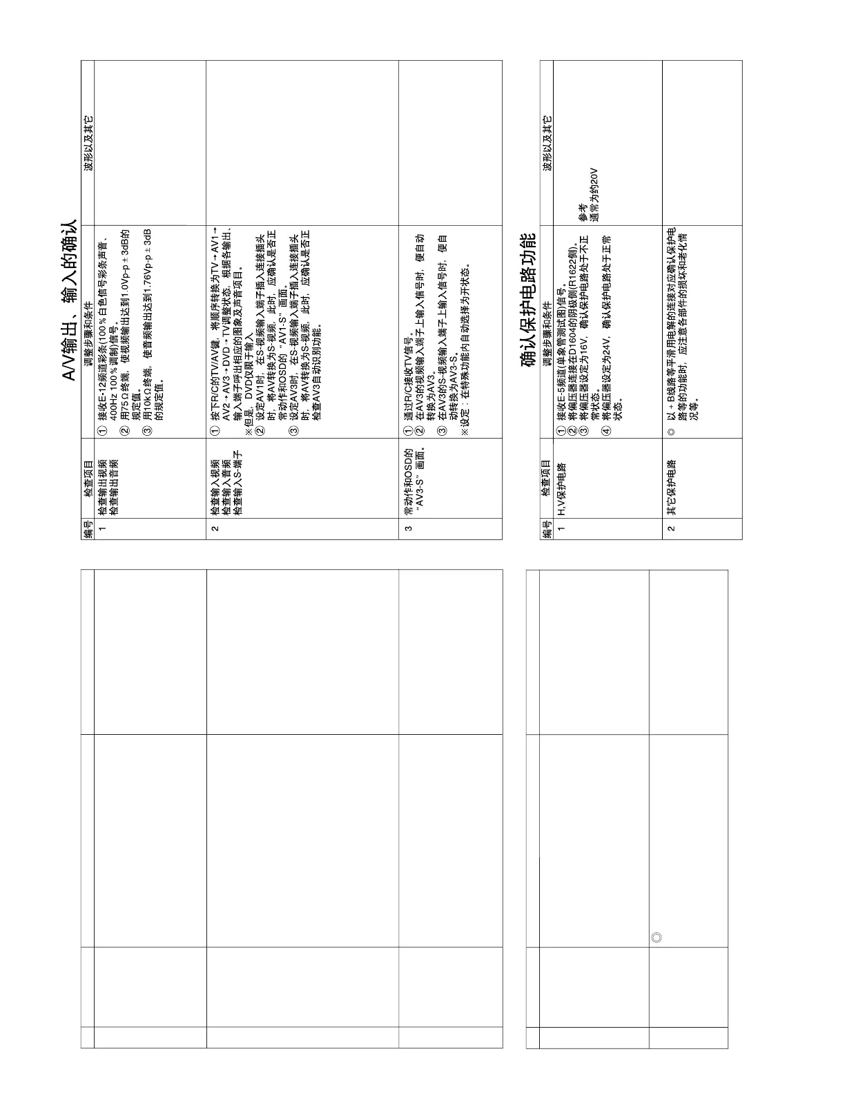
NO. Check item Adjusting procedure and conditions Waveform and others
H, V protector 1 Receive E-5CH (monoscope pattern).
2 Connect the bias box to the cathode side
(R1622 side) of D1604.
3 Set the voltage of the bias box at 16V, and verify
that the protector does not operate.
4 Set the voltage of the bias box at 24V, and verify
that the protector operates.
PROTECTOR OPERATION CHECK
Correspondence for short circuit of
smoothening electrolysis of +B line and so on
To check the operation of the protector and
so on, take care for the breakage, deteriora-
tion and so on of each element.
Other protectors
1
2
Reference Approx. 20 V as ordinary
A/V INPUT/OUTPUT CHECK
NO. Check item Adjusting procedure and conditions Waveform and others
Video output
check
Audio output
check
1
3 AV3 automatic
discrimination
check
1 Receive TV with R/C.
2 When the signal is input to the video input ter-
minal of AV3, it is automatically switched to AV3.
3 When the signal is input to the S-video input
terminal of AV3, it is automatically switched to
AV3-S.
* Setting: Auto select in the feature — ON
Video input
check
Audio input
check
S-terminal input
check
1 The mode must be switched in the cycle of TV
→ AV1 → AV2 → AV3 → DVD → TV with TV/
AV key of R/C, and the image and voice which
correspond to each input/output terminals must
be properly output.
* Here, DVD is applied for the input alone.
2 When the connector is inserted into the S-video
input terminal on AV1, it must be switched from
AV to S-video and must be properly operated.
Moreover,
check “AV1-S” of OSD.
3 When the connector is inserted into the S-video
input terminal on AV3, it must be switched from
AV to S-video and must be properly operated.
Moreover,
check “AV3-S” of OSD.
2
1 Receive E-12CH colour bar (colour bar audio
400Hz 100% MOD of 100% white).
2 The video output must be within the specified
range of 1.0Vp-p ± 3dB at the 75Ω terminator.
3 The audio output must be within the specified
range of 1.76Vp-p ± 3dB at the 10kΩ termina-
tor.