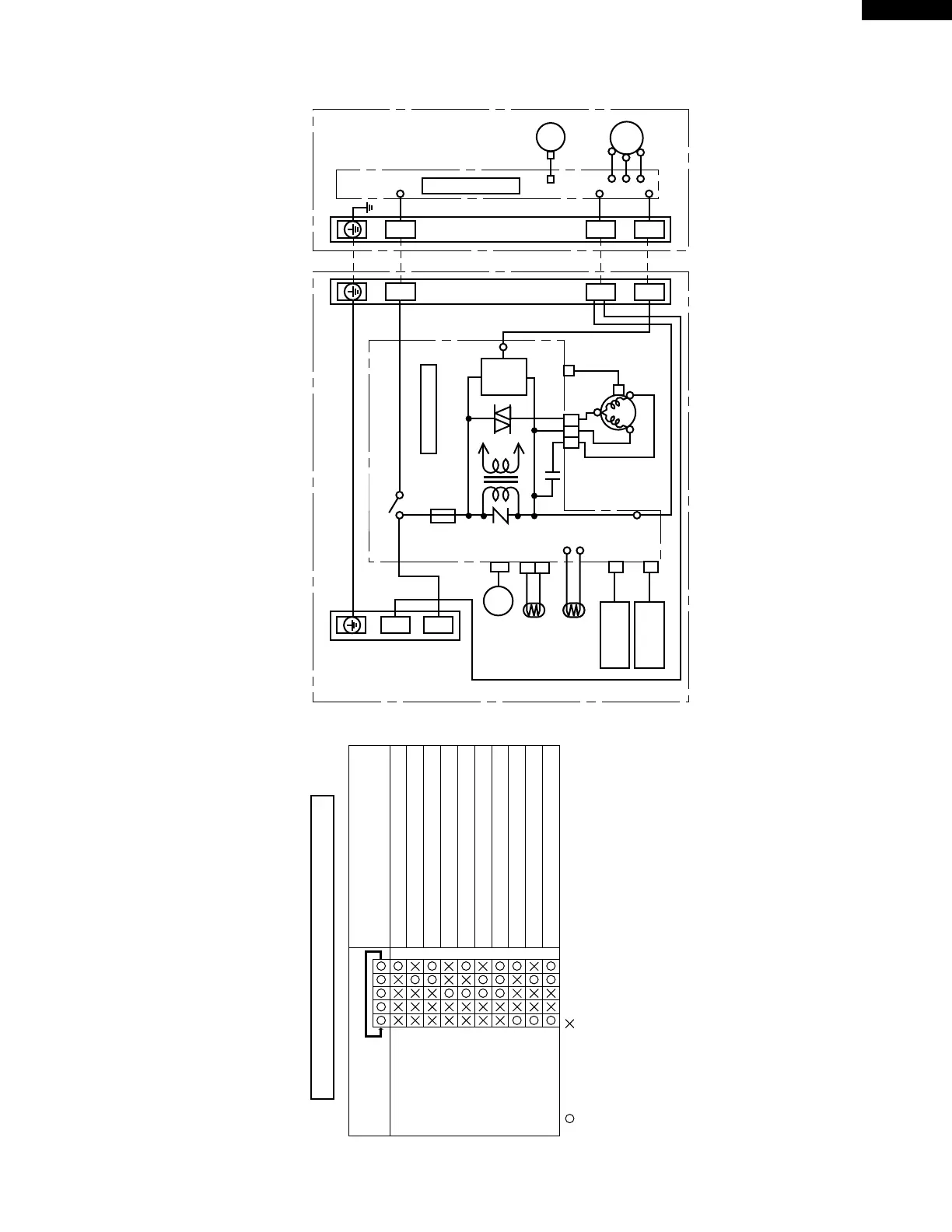
Figure W-1. Wiring Diagram for AH-X127E and AY-X127E
TERMINAL BOARD
GREEN-YELLOW
POWER
SUPPLY
LOUVER
MOTOR
ROOM TEMP
THERMISTOR
PIPE TEMP
THERMISTOR
FAN MOTOR
CAPACITOR
430V 1.5µF
RECEIVER
BOARD UNIT
DISPLAY
BOARD UNIT
ORANGE
YELLOW
TH1
CN4
CN7 CN8
CN1
A
CN2
BLUE
BLUE
BLUE
FAN MOTOR
CN3
NR1
TH2
TH2-1
TH2-2
1
2
BLACK
M
A
C1
TR
5 3 1
RED
RED
C
S
R.P.M.
SIGNAL
CONTROL BOARD UNIT
FUSE
250V 2.5A
T
OutIn
SSR1
BROWN
RY1
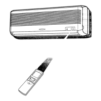
INDOOR UNIT
BLACK
TERMINAL BOARDTERMINAL BOARD
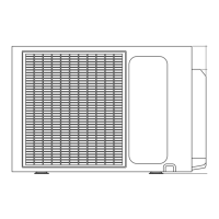
OUTDOOR UNIT
FAN MOTOR
COMPRESSOR
UNIT TO UNIT CORD
CONTROL BOARD UNIT
1 1
2 2
N N
L
N
SERIAL
SIGNAL
CIRCUIT
LED INDICATION FOR SELF-DIAGNOSIS
Abnormal conditions
Short circuit of the outdoor thermistor
Overheat of the compressor
Abnormal AC current
Compressor lock
Open circuit of the outdoor thermistor
DC overcurrent or over heat of the IPM
AC overcurrent
Open circuit of serial signal line
Short circuit of serial signal line
Abnormal fan motor of indoor unit
<Indication of the abnormal condition>
LED yellow and LED red indicate automatically,
if the set is in abnormal condition.
: LED no blink: LED blink
<LED yellow bliking>
LED yellow blinks 5
times in 10 seconds.
Blink steps
<LED red blinking>
Abnormal condition is
indicated by the blink-
ing pattern of LED red.