3
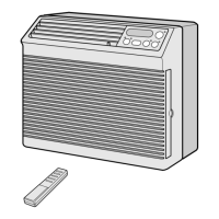
AF-T908X
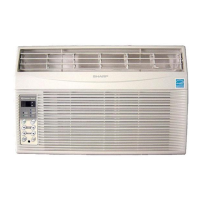
AF-R908X
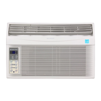
AF-R1108X
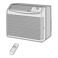
AF-R1208X
ELECTRICAL PARTS
Models AF-T908X,AF-R908X AF-R1108X AF-R1208X
Running capacitor 370V-35µF 370V-40µF 370V-60µF
Fan capacitor(indoor/outdoor)
250V-3µF/250V-6µF 250V-6µF/250V-6µF 250V-6µF/250V-6µF
Thermistor 15kΩ at 78˚F
Fan motor RMLA046/RMLA045 RMLA044/RMLA043 RMLA044/RMLA043
Overload relay MRA12061-9201 MRA98965-9200 MRA12053-9200
Figure W-1 .
WIRING DIAGRAM
POWER SUPPLY CORD
CONTROL BOARD UNIT
DISPLAY
BOARD
UNIT
115V
60HZ
RIBBED
COMPRESSOR
NON
RIBBED
4A
125V
OVERLOAD
RELAY
GR
BK
BK
C
1
1
2
3
4
3 5 7
R
RE WH
RUNNING
CAPACITOR
INDOOR
FAN MOTOR
FAN MOTOR
CAPACITOR
(INDOOR)
THERMAL
PROTECTOR
S
T1
RE OR WH
MRY
OUT
FU1 NR
BCN1
WIRE COLOR
BK : BLACK
BL : BLUE
RE : RED
WH : WHITE
GR : GREEN
GY : GRAY
OR : ORANGE
YELLOW
ORANGE
THERMISTOR
(ROOM TEMP.)
THERMISTOR
(PIPE TEMP.)
C1
TR
CN1 CN2
CN3
CN4
BCN2
BCN3
IN
GY
GR
BK
BL
A.C
H
M
L
M.C
CNR1
CNR2
CNR3
CNR4
CNR5
RY1
RY2
RY3
RY4
RY5
GY
GY
1 3 5
OUTOOR
FAN MOTOR
FAN MOTOR
CAPACITOR
(OUTDOOR)
THERMAL
PROTECTOR
RE
WH
GR
BK
BL
A.C
H
L
M.C
GY
MEGGER TESTING
Check the resistance between connector terminal and motor shaft.
Reading must be more than 10MΩ at DC 500V.
(2) Connect RED and GRAY wires to proper source and
make run test by rotating the motor shaft by hand.
MODEL
Indoor fan motor
MAIN COIL
SUB COIL
CON1
CON2
AF-R908X, AF-T908X
approx. 58.95 Ω approx. 102.16 Ω
approx. 87.89 Ω approx. 77.26 Ω
approx. 34.75 Ω approx. 18.16 Ω
approx. 11.89 Ω approx. 12.30 Ω
AF-T1108X, AF-T1208X
MODEL
Outdoor fan motor
MAIN COIL
SUB COIL
CON1
AF-R908X, AF-T908X
approx. 51.40 Ω approx. 38.06 Ω
approx. 29.30 Ω approx. 37.32 Ω
approx. 21.10 Ω approx. 25.22 Ω
AF-T1108X, AF-T1208X
FAN MOTOR
(1) Using a volt-ohm-meter set on resistance range, check the resistance between the motor windings.
THERMAL
PROTECTOR
OFF 125˚C
BLACK
GRY
GRY
CAP
BLUE
Indoor fan motor
MAIN
CON1
LOW
WHITE
HI
RED
115V, 60Hz
THERMAL
PROTECTOR
OFF 125˚C
BLACK
SUB
CAP
BLUE
Outdoor fan motor
MAIN
SUB
CON1 CON2
LOW
WHITE
MID
ORANGE
HI
RED
115V, 60Hz