Do you have a question about the Sharp AH-G13 and is the answer not in the manual?
Detailed specifications for the AH-G13/AU-G13 model including electrical and fan data.
Detailed specifications for the AH-PG15/AU-PG15 model including electrical and fan data.
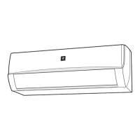
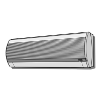
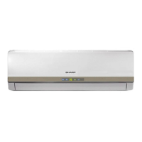
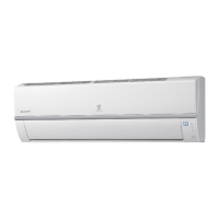
Diagrams showing external dimensions for the indoor units.
Diagrams showing external dimensions for the outdoor units.
Electrical wiring diagram specific to the AH-G13 indoor unit.
Electrical wiring diagram specific to the AH-PG15 indoor unit.
Electrical wiring diagram for the outdoor units.
List of electrical components for AH-G13/AU-G13 models with models and remarks.
List of electrical components for AH-PG15/AU-PG15 models with models and remarks.
Detailed electronic control diagram for the AH-G13 indoor unit.
Printed wiring diagram for the AH-G13 indoor unit control board.
How thermostat lines control temperature in COOL and DRY modes.
Details on COOL operation modes, compressor, and fan control.
Indoor fan speed settings for various modes and models.
Unit behavior upon power supply and restart after power failure.
Sequence and outputs for the AH-G13 test mode.
Sequence and outputs for the AH-PG15 test mode.
Steps for diagnosing faults and associated timing charts for fault indication.
Troubleshooting steps when the remote controller does not operate the unit.
Troubleshooting steps for issues related to remote controller signal and batteries.
A visual representation of the air conditioner's refrigeration cycle.
Standard operating conditions and graphical performance curves.
Steps to open the front panel and remove the cord clamp from the indoor unit.
Procedures for disconnecting unit-to-unit wiring and removing air filters.
Steps for removing screw covers, louvers, and other casing parts of the indoor unit.
Procedures for removing the LED guide and display board assembly from the indoor unit.
Steps to disconnect the thermistor and remove its holder from the indoor unit.
Procedures for removing the evaporator assembly and drain guide from the indoor unit.
Steps to remove the cross flow fan from the indoor unit.
Steps to loosen screws for the side and terminal covers of the outdoor unit.
Procedures for disconnecting the unit-to-unit cord and removing the top panel.
Procedures for removing the special nut and the control box from the outdoor unit.
Detailed steps for disassembling the fan unit.
Detailed steps for assembling the compressor cover.
This document is a service manual for Sharp split system room air conditioners, specifically models AH-G13 and AH-PG15 for indoor units, and AU-G13 and AU-PG15 for outdoor units. It provides comprehensive information for service and maintenance, covering product specifications, external dimensions, wiring diagrams, electrical parts, microcomputer control system, functions, troubleshooting, refrigeration cycle, performance curves, disassembling procedures, and a replacement parts list.
The device is a split system room air conditioner designed for cooling. It operates by controlling the compressor and fan motors based on room temperature and preset temperature settings. The unit features various operation modes including COOL and DRY, with automatic fan speed control and a freeze preventive function. It also incorporates timer functions (ON/OFF and 1-hour timer) and an auto-restart feature in case of power failure. A test mode is available for diagnostic purposes.
The AH-G13/AU-G13 and AH-PG15/AU-PG15 models share identical specifications:
| Brand | Sharp |
|---|---|
| Model | AH-G13 |
| Category | Air Conditioner |
| Language | English |