GB-1
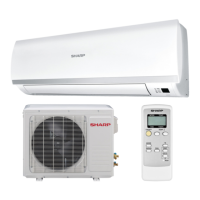
INSTALLATION DIAGRAM
NOTES ON LOCATIONS
Provide as much installation space as possible for efcient
air-conditioning.
5.9 inch (150 mm) or more
11.8 inch (300 mm)
or more
Indoor unit
1. Keep the air outlet clear of any obstacle so that outgoing air ows
smoothly in the entire room.
2.
Make a drain hose hole that will allow easy condensate water drain-
age.
3.
Provide sufcient space on
both sides and above the unit.
4. The unit must be installed with enough space allowance so that the
air lters can be removed and replaced easily.
5.
Keep TV set, radio and other similar appliances at least 3.3 feet (1
m) or more away from the unit and the remote control.
6. Keep the air inlet clear of obstacles that could block incoming air,
and clean the air lter regularly.
7.
The remote control may not function properly in a room equipped
with
an electronic simultaneous-start or rapid-start uorescent
lighting.
8.
Select a location that does not cause loud operation noise
and ex-
treme vibrations.
Outdoor unit
1. Place the outdoor unit on a stable base.
2.
Provided
sufcient space around the unit. It should also be well venti-
lated.
3.
The unit should not be exposed to strong wind nor splashed with
rain
water.
4. Water should be drained from the unit.
Lay a drain hose if required.
In cold regions, installation of
the drain pipe is not
advisable as
freezing could result.
5.
Keep TV sets, Radios and other related electronic appliances at
least 3.3 feet (1 m) away from the unit.
6. Avoid locations exposed to machine oil vapor, salty air (facing the
seashore,
for example), hot spring vapor sulfur gas, etc. Such loca-
tion can cause
breakdown.
7.
Avoid locations exposed to muddy water (along a road, for example)
or
where the unit can be tampered with.
8.
Select a location where the outgoing air or operating noise cannot
annoy
others.
9. Keep the air outlet opening free of any obstacle. This could affect the
performance of the unit and create loud noises.
10
.For colder climate areas, install the unit in a location not affected
by snow or ice falls (example: roof houses). Unit should be installed
minimum 10 inches (25 cm) from ground level or follow your coun-
try’s average snowfall accumulation.
Carefully read and follow these instructions for smooth and trouble-free installation.
Coating tape
(Commercially
available)
ENGLISH
SAFETY PRECAUTIONS
•Tightenthearenutwithatorquewrenchaccordingtothespecied
method.
If the are nut is tightened too hard, the are nut may be broken after a
long time and cause refrigerant gas leakage.
•Wheninstallingtheunit,donottoaddanairsubstanceotherthan
thespeciedrefrigerant(R410A)intherefrigerantcycle.
Otherwise, it will cause burst and injury as a result of abnormal high pres-
sure in the refrigerant cycle.
•Besuretoconnecttherefrigerantpipebeforerunningthecompres-
sor.
Otherwise, it may burst and cause injury as a result of abnormal high pres-
sure in the refrigerant cycle.
• Ground the unit.
Incomplete ground may cause electrical shock.
•InstallaGroundFaultInterrupt(GFI)circuitbreakerdependingon
theinstallationlocationoftheunit(suchashighlyhumidareas).
If GFI breaker is not installed, it may cause electric shock.
•Arrangethedrainhosetoensuresmoothdrainage.
Insufcient drainage may cause wetting of the room, furniture etc.
• ThisroomairconditionerusesrefrigerantR410A.
Use the pipe, are nut and tools exclusively for R410A.
•Installationmustbemadeinaccordancewiththeinstallation
manualbyqualiedservicepersonnel.
Incorrect work will cause electric shock, water leak, re.
•Besuretousetheattachedaccessoriespartsandspecied
partsforinstallation.
Use of other parts will cause electric shock, water leak, re, the unit
falling.
•Theapplianceshallbeinstalledandwiredinaccordancewith
NationalElectricalCodeandbyqualiedpersonnelonly.
Wrong connection can cause overheating or re.
•Afterinstallationhascompleted,checkthatthereisnoleakage
ofrefrigerantgas.
If the refrigerant gas contact with re, it may generate toxic gas.
•Ventilatetheroomifrefrigerantgasleaksduringinstallation.
If the refrigerant gas contact with re, it may generate toxic gas.
•Usethespeciedelectricalcable.
Make sure the cable is secured in place and that the terminals are
free of any excess force from the cable. Otherwise overheating or
re may result.
•Formthecablesothatthecontrolboxcover,thecordholder
andcableholderarenotloose.
Otherwise overheating, re or electric shock may result.
5.9 inch (150 mm)
or more
5.9 inch (150 mm)
or more
19.7 inch (500 mm)
or more
78.7 inch (2000 mm)
or more
19.7 inch (500 mm) or more
11.8 inch (300 mm)
or more
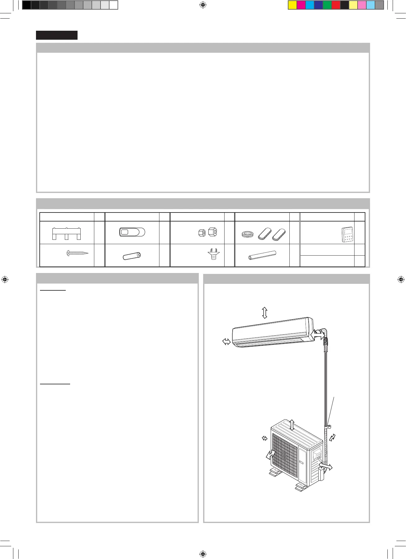
ITEMS
Q’ty
ITEMS
Q’ty
ITEMS
Q’ty
ITEMS
Q’ty
ITEMS
Q’ty
1 MOUNTING PLATE
1
3 REMOTE CONTROL
1
5 FLARE NUT
(1/4”, 5/8”)
1
set
7 BASE PAN CAP
1
set
9 WIRED CONTROL KIT
(Included with the
outdoor unit)
1
set
2 LONG SCREW
(M4.2 x 25)
To x the mounting plate
.
7
4 DRY BATTERY
2
6
DRAIN HOSE
ADAPTER
(Included with the
outdoor unit)
1
8
INSULATION
1
10
OPERATION MANUAL
1
11
INSTALLATION MANUAL
1
ACCESSORIES
AYX36RU_IM_3_lang.indb 1 2014-09-12 07:59:32