EasyManua.ls Logo

Sharp CD-XP5500

Sharp CD-XP5500
64 pages
To Next Page IconTo Next Page
Loading...
CD-XP500/CD-XP5500
No. S1205CDXP500/
CONTENTS
Page
IMPORTANT SERVICE NOTES (FOR U.S.A. ONLY)....................................................................................................... 2
SPECIFICATIONS ............................................................................................................................................................. 3
NAMES OF PARTS ........................................................................................................................................................... 4
OPERATION MANUAL ...................................................................................................................................................... 6
QUICK GUIDE ................................................................................................................................................................... 8
DISASSEMBLY................................................................................................................................................................ 10
REMOVING AND REINSTALLING THE MAIN PARTS................................................................................................... 13
ADJUSTMENT ................................................................................................................................................................. 14
NOTES ON SCHEMATIC DIAGRAM .............................................................................................................................. 18
TYPES OF TRANSISTOR AND LED............................................................................................................................... 18
BLOCK DIAGRAM ........................................................................................................................................................... 19
SCHEMATIC DIAGRAM / WIRING SIDE OF P.W.BOARD ............................................................................................. 22
VOLTAGE ........................................................................................................................................................................ 39
WAVEFORMS OF CD CIRCUIT ...................................................................................................................................... 40
TROUBLESHOOTING ..................................................................................................................................................... 41
FUNCTION TABLE OF IC................................................................................................................................................ 45
FL DISPLAY ..................................................................................................................................................................... 51
REPLACEMENT PARTS LIST/EXPLODED VIEW
PACKING OF THE SET (FOR U.S.A. ONLY)
SERVICE MANUAL
This document has been published to be used
for after sales service only.
The contents are subject to change without notice.
SHARP CORPORATION
In the interests of user-safety the set should be restored to its
original condition and only parts identical to those specified be
used.
MINI COMPONENT SYSTEM
MODEL CD-XP500
CD-XP500 Mini Component System consisting of CD-XP500
(main unit) and CP-XP500 (speaker system).
MINI COMPONENT SYSTEM
MODEL CD-XP5500
CD-XP5500 Mini Component System consisting of CD-XP5500
(main unit) and CP-XP5500 (speaker system).
Question and Answer IconNeed help?

Do you have a question about the Sharp CD-XP5500 and is the answer not in the manual?

Sharp CD-XP5500 Specifications

General IconGeneral
BrandSharp
ModelCD-XP5500
CategoryStereo System
LanguageEnglish

Summary

IMPORTANT SERVICE NOTES

BEFORE RETURNING THE AUDIO PRODUCT (Fire & Shock Hazard)

Safety checks to perform before returning the unit to the user.

SPECIFICATIONS

General

Power source, consumption, dimensions, and weight of the unit.

Amplifier

Output power and speaker/headphone specifications.

CD player

Type, signal readout, D/A converter, frequency, and dynamic range.

Tuner

FM and AM frequency ranges.

Cassette deck

Frequency response, S/N ratio, and wow/flutter.

CP-XP500 CP-XP5500 (Speakers)

Speaker system type, input power, impedance, dimensions, and weight.

NAMES OF PARTS

Display

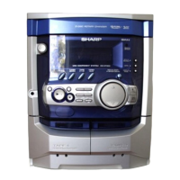
List and identification of indicators on the unit's display.

Front panel

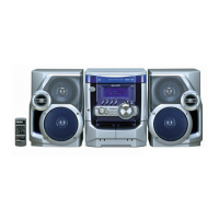
Identification of controls and connectors on the front of the unit.

Rear panel

Identification of connectors and ports on the rear of the unit.

Remote control

Identification of buttons and functions on the remote transmitter.

CP-XP500 CP-XP5500 (Speakers)

Identification of speaker components like tweeter and woofer.

OPERATION MANUAL

Setting the clock

Step-by-step instructions for setting the unit's clock.

Troubleshooting chart

General Issues

Common issues and their possible causes and solutions.

Cassette Deck Problems

Specific troubleshooting for cassette deck problems.

Remote Control Issues

Troubleshooting steps for remote control operation issues.

CD Player Problems

Troubleshooting steps for CD player playback problems.

Tuner Reception Problems

Troubleshooting steps for tuner reception issues.

Condensation Issues

Causes and solutions for condensation issues affecting unit performance.

Troubleshooting chart (Continued)

Handling Malfunctions

General steps to take when the unit malfunctions.

Clearing Memory (Reset)

Procedure to reset the unit and clear all stored data.

Transportation Preparation

Instructions for preparing the unit for transportation to prevent damage.

QUICK GUIDE

Included Accessories

List of included accessories with the system.

System Connections

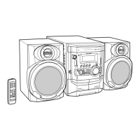
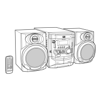
Diagram and instructions for connecting the system components.

Remote Control Battery Installation

Steps for installing batteries in the remote control.

Initial System Power-On

Initial setup and powering on the audio system.

Playing CDs

How to play music from a compact disc.

Tuning Radio Stations

Instructions for tuning into radio stations.

Playing Cassette Tapes

How to play audio from cassette tapes.

DISASSEMBLY

REMOVING AND REINSTALLING THE MAIN PARTS

TAPE MECHANISM SECTION

Procedures for removing and reinstalling tape mechanism components.

ADJUSTMENT

Tape Speed Adjustment

Procedures and specifications for adjusting tape speed.

Torque Check

Specifications for checking tape mechanism torque.

TUNER SECTION Adjustments

Adjustment procedures for the tuner section.

CD SECTION Adjustments

Automatic adjustment functions for the CD playback system.

TEST MODE

Setting the Test Mode

Instructions on how to enter and set up various test modes.

Error Message Display Contents

NOTES ON SCHEMATIC DIAGRAM

TYPES OF TRANSISTOR AND LED

BLOCK DIAGRAM

SCHEMATIC DIAGRAM

WIRING SIDE OF P.W.BOARD

VOLTAGE

WAVEFORMS OF CD CIRCUIT

TROUBLESHOOTING (CD Issues)

CD Player Not Functioning

Steps to diagnose and resolve issues with the CD player not operating.

CD Playback Failure

Procedures for diagnosing why a CD is not playing correctly.

Focus-HF System Check

Steps to check the focus and HF signal system for CD playback issues.

Tracking System Check

Steps to check the tracking system's performance using waveforms.

Spin System Check

Steps to check the turntable rotation and spin motor system.

PLL System Check

Steps to check the PLL system for CD signal processing.

Sound Output Issues

Troubleshooting steps for sound issues like no output or dropouts.

FUNCTION TABLE OF IC

IC1 CD Servo (LC78645 NE) Pin Functions

Pin functions and settings for the CD Servo IC.

IC601 Audio Processor (LC75341) Pin Functions

Pin functions for the Audio Processor IC.

IC701 System Microcomputer (IX0524 AW) Pin Functions

Pin functions and settings for the System Microcomputer IC.

FL DISPLAY

Grid Assignment

Layout and assignment of segments for the FL display grid.

Anode Connection

Wiring connections for the FL display anodes.

SHARP PARTS GUIDE

Ordering Replacement Parts

Information required for ordering replacement parts from SHARP.

Capacitor and Resistor Codes

Codes and explanations for identifying capacitor and resistor components.

Related product manuals