9
9-1 9-2
CX51N3/N4
1. Receive the "PAL Color Bar" signal.
2. Press R/C to set Picture Normal condition.
3. Connect the oscilloscope to
Red cathode(D882 Chathode).
» Range : 20 V/div. (AC) (Using 10:1 probe)
» Sweep time : 10 µsec/div.
4. Using the R/C call "SUB COL" in SERVICE
mode. Adjust SUB COLOUR bus data, so that
the 75% White & Red portions of PAL Color
Bar be at the same level shown as Fig. 1-1.
* Before adjust SUB-COL, make sure COL-
OP=8, COL-O3=4, COL-O4=4. After adjust
SUB-COL,set COL-OP=14, COL-O3=10,
COL-O4=10.
5. Clear the SERVICE mode.
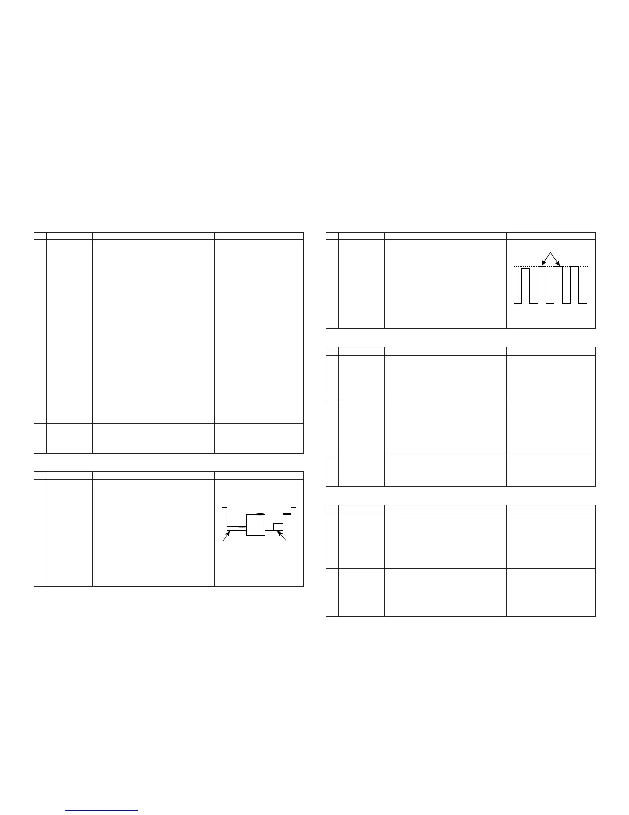
HORIZONTAL AND VERTICAL DEFLECTION LOOP ADJUSTMENT
NO. Adjustment part Adjusting procedure and conditions Waveform and others
1
2
3
4
5
6
V-SLOPE (I
2
C
BUS CON-
TROL)
V-SHIFT-50
(I
2
C BUS
CONTROL)
V-AMP50
(I
2
C BUS
CONTROL)
H-SHIFT (50)
(H-CENTER)
S-CORREC-
TION (I
2
C BUS
CONTROL)
SUB-
SHARPNESS
1. Receive Monoscope Pattern Signal.
2. Call the "V-LIN" mode.
3. Increase or decrease "V-LIN" by Volume key
till the horizontal line in the center of
monoscope is just at the position where the
blanking starts.
1. Call the "V-CENT" mode.
2. Increase or decrease "V-CENT" by Volume key
till the picture is centered.
1. Call the "V-AMP" mode.
2. Increase or decrease "V - AMP" by Volume
key to set overscan of 9.5% typical.
Adjustment Spec 9.5% range +1% -0%.
1. Call the "H-CENT" mode.
2. Increase or decrease "H-CENT" by Volume key
to center the picture horizontal.
1. SET DATA TO 20
* Check the E-5 CH Monoscope Pattern then re-
adjust V-Slope, V-Shift and V-Amp to makesure
adjustment is in acceptable Ring-Shaped.
1. SET DATA TO 20
PAL CHROMA ADJUSTMENT
NO. Adjustment part Adjusting procedure and conditions Waveform and others
1 SUB COLOUR
(I
2
C BUS
CONTROL)
1 Focus 1. Receive the "Monoscope Pattern" signal.
2. Press R/C to set Picture NORMAL condition.
3. Adjust the focus control to get the best focus-
ing.
Fig. 1-1
NTSC CHROMA ADJUSTMENT
NO. Adjustment part Adjusting procedure and conditions Waveform and others
1 SUB-TINT
(I
2
C BUS
CONTROL)
1. Receive the "NTSC3.58 Colour Bar" signal thru
AV in.
2. Connect the oscilloscope to TP47B (P882 pin
5) BLUE-OUT.
»
Range : 100mV/div. (AC) (Use Probe 10:1)
»
Sweep time: 10 µsec/div.
3. Call the "SUB-TINT" mode in service mode.
Adjust the "SUB-TINT" bus data to obtain the
waveform shown as Fig. 1-1.
4. Clear the SERVICE mode.
PROTECTOR OPERATION CHECKING
NO. Adjustment part Adjusting procedure and conditions Waveform and others
1 BEAM
PROTECTOR
1. Receive "Monoscope Pattern" signal.
2. Set CONTRAST MAX.
3. Set BRIGHT MAX.
4. During the Collector & Emitter of Q883/5/7
short, make sure the protector ON and switch
to standby mode.
* Select one of Q883/5/7 to do
each short test.
2H.V
PROTECTOR
1. Receive "Monoscope Pattern" signal.
2. Connect output of Bias Box to D603 cathode
(R610 side).
3. Set voltage of Bias Box to 18V and make sure
the protector is not work.
4. Set voltage of Bias Box to 27V, and make sure
the protector is work.
A/V INPUT AND OUTPUT CHECKING
NO. Adjustment part Adjusting procedure and conditions Waveform and others
1
VIDEO AND
AUDIO OUT-
PUT CHECK
1. Receive the "PAL Color Bar" signal (100%
White Color Bar, Sound 400 Hz 100% Mod).
2. Terminate the Video output with a 75 ohm im-
pedance. Make sure the output is as specified
(1.0 Vp-p ±3 dB).
3. Terminate the Audio output with a 10k ohm im-
pedance. Make sure the O/P is as specified
(1.76 Vp-p ±3 dB).
2 VIDEO AND
AUDIO INPUT
CHECK
1. Using the TV/AV key on the remote controller,
make sure that the modes change in order of
TV, AV & TV again and the video & audio out-
put are according to the input terminal for each
mode.If connect input to Front and Rear AV
terminal, input terminal of Front AV will be se-
lected.
3 Other
protectors
1. Once finish rectified Electrolytic Capacitor short
testing in +B line, check all possible damaged
components on +B line.
(Use random selected set for inspection)
Fig. 1-1
W
Y
Cy G Mg R
B
SAME LEVEL
Cy
G
B
W
Y 100%W
75%
Mg R