'@
Step
Signal Mode
Instrument
Oscilloscope Remarks
connection
~-GND
V'
n 0
By
the
reception of
the
infrared
<§>-GND
of
remote
control,
the
signal of
1
-
Power on
0-
GND
the
distance lens is as shown at
U U L
left.
<t>-
GND
Table 2 Check
of
the
photodiodes
Step
Signal
Mode
Instrument
Specified value
Remarks
connection
LO
Service
<g>-GND
1.8<
V < 2.3
1
position 2
<D>-GND
LM
170<mV<220
2
LO
Power on
~-GND
OV ± O.2V No light
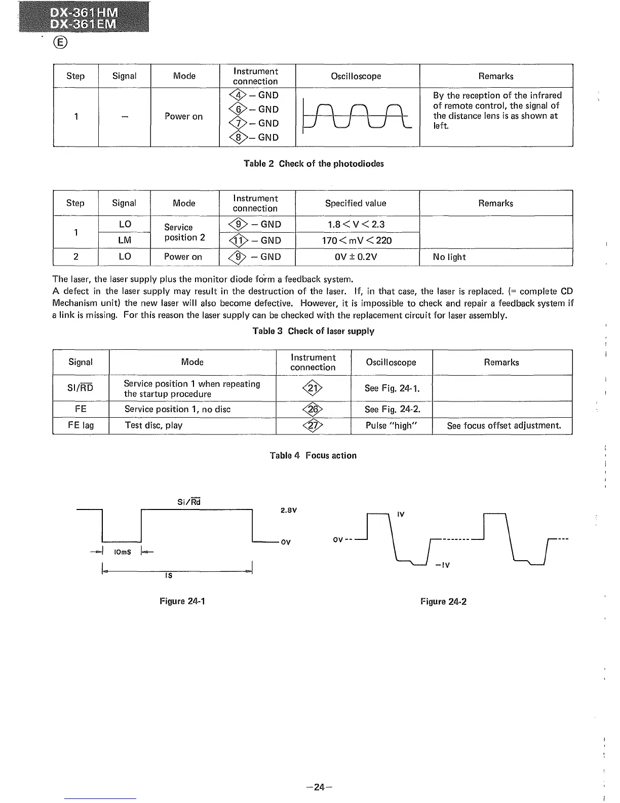
The
laser,
the
laser supply plus
the
monitor
diode form a feedback system.
A
defect
in
the
laser supply may result in
the
destruction of
the
laser. If, in
that
case,
the
laser is replaced. (=
complete
CD
Mechanism unit)
the
new laser will also become defective. However, it is impossible to
check
and repair a feedback system if
a link is missing.
For
this reason
the
laser supply can be checked with
the
replacement circuit for laser assembly.
Table
3 Check of laser supply
Signal Mode
Instrument
Oscilloscope Remarks
connection
SI/RD
Service position 1 when repeating
<S>
See Fig. 24-1.
the
startup
procedure
FE
Service position 1, no disc
<S>
See Fig. 24-2.
FE lag Test disc, play
4J>
Pulse
"high"
See focus
offset
adjustment.
Table 4 Focus action
Si/Rd
----l
10mS
I--
I
..
IS
Figure 24-1
-24-
OV
--
Figure 24-2