EasyManua.ls Logo

Sharp DX-361HM - User Manual

Sharp DX-361HM
66 pages
To Next Page IconTo Next Page
Loading...
SERVICE
MANUAL/
SERV'CEaANLEITUNG/
MANUEL
DE
SERVICE
INDEX TO CONTENTS
-------------..
Page
PHOTO: DX-361HM(GY}
®
SAFETY REGULATIONS
'2,3
IMPORTANT SERVICE NOTES (DX-361 EM
ONLY}········4
WIRING PRIMARILY SUPPLY LEADS
(DX-361EM ONLY) · · ·4
SPECIFICATIONS
..........•....•.•...............
'5,6
NAMES OF PARTS
.•.•......•..•....•.•..........
'5,6
PLAYING A DISC
..............•................
'7-12
DISASSEMBLY
'13,14
REPLACEMENT OF PICKUP
'15,16
FITTING OF DISC HOLDER· ·
..
"15,16
BLOCK DIAGRAM
...........•.•.....•......
,
,17
TROUBLESHOOTING
.•............
,.,
...•......
'18-37
S5044DX361 HEM
Inthe interests of user-safetythe set should be restored to its original
condition and only parts identical to those specified be used.
1m Interesse der Benutzer-Sicherheit solite dieses Gerst
wieder
auf seinen ursprOnglichen Zustand eingestellt und nur die vorge-
schriebenen Teile verwendet werden.
· Dans l'interet de la securite de I'utilisateur, l'appareil devra etre
reconstitue dans sa condition premiere et seules des pieces
identiques acelles speciliees. doivent etre utilisees,
Page
SERVICE LOOP"
•.........•....
,
'38-40
CIRCUIT DESCRIPTION' , , , '41
ADJUSTMENT
.......•.......
, , ,
'42,43
NOTES ON SCHEMATIC
DIAGRAM···········,·······
·44
SCHEMATIC DIAGRAM/WIRING SIDE OF
P.W.BOARD
.,
, '
'45-50
EXPLODED VIEW " , , '51
FUNCTION TABLE OF IC , ,
'52-64
PACKING METHOD (DX-361 EM ONLY)
·65
REPLACEMENT PARTS L1JT
'66-69
SERVICE INFORMATION
".,
.••.
,."
..
"",.",
,70
Seite
EINSTELLUNG ,
'42,43
ANMERKUNGEN ZUM SCHEMATISCHEN
SCHALTPLAN , ,
·44
SCHEMATISCHER SCHALTPLAN/VERDRAHTUNGS-
SEITE DER LEITERPLATTE · · ·
..
·
"45-50
EXPLOSIONSDARSTELLUNG , '51
FUNKTIONSTABELLE DES INTEGRIERTEN
SCHALTKREISES
,.,
,.
52-64
ERSATZTEILLISTE , , ,
'66-69
SERViCE-INFORMATION,···············,··········
'70
Page
DESCRIPTION DES CIRCUIT
..
, , ,
,.
·41
REGLAGE
.......•..............
,
'42,43
REMARQUES CONCERNANT LE
DIAGRAMME SCHEMATIQUE
'44
DIAGRAM ME SCHEMATIQUE/COTE CABLAGE DE
LA PLAQUETTE DE MONTAGE IMPRIME
'45-50
VUE EN
ECLATE························,··········
'51
TABLEAU DE FONCTIONS DE CI ,
..
,
'52-64
L1STE
DES PIECES DE
RECHANGE
,."
'66-69
INFORMATION DE
SERViCE··,····,·················
·70
INHAL
TSVERZEICHNIS
@
Seite
SICHERHEITSVORSCHRIFTEN·······················
'2,3
TECHNISCHE DATEN , , ,
'5,6
BEZEICHNUNG DER TEILE ,
'5,6
ABSPIELEN EINER DISC , , ,
'7-12
ZERLEGEN
,
..
" ,
•......
, ,
,.
'13,14
AUSWECHSELN DES ABTASTERS ,
'15,16
EINPASSEN DES
DiSC-HALTERS········,········
'15,16
BLOCKSCHALTPLAN ,
..
,
.•........
,
,17
FEHLERSUCHE
,
..
'18-37
SERVICE-SCHLEIFE , ,
'38-40
SCHALTUNGSBESCHREIBUNG· , 41
TABLE DES MATIERES
(f)
Page
PRESCRIPTIONS RELATIVES A LA
SECURITE·········
'2,3
CARACTERISTIQUES
....•........................
'5,6
NOMENCLATURE,································
'5,6
LECTURE DU DISQUE , ,
..
7
-12
DEMONTAGE····,············
..
·················
'13,14
REMPLACEMENT DU PORTE-LASER
'15,16
FIXATION DU PORTE-DISQUE
"15,16
DIAGRAMME SYNOPTIQUE , , ,
..•
·17
DEPANNAGE
............•...............
,
'18-37
SCHEMA DE REVISION
..
,
'38-40
SHARP CORPORATION
Question and Answer IconNeed help?

Do you have a question about the Sharp DX-361HM and is the answer not in the manual?

Sharp DX-361HM Specifications

General IconGeneral
TypeCD Player
Power Consumption12 W
Channels2
Frequency Response20Hz - 20kHz
Output Level2V RMS

Summary

Safety and Precautions

General Safety Regulations

Essential safety rules for handling and servicing the device.

Laser Safety Precautions

Critical warnings and precautions regarding laser beam exposure.

Service Information

Important Service Notes (DX-361 EM Only)

Key notes for service technicians, specific to DX-361EM model.

Wiring Primary Supply Leads (DX-361 EM Only)

Guidelines for connecting primary supply leads for the DX-361EM model.

Specifications and Parts Identification

Technical Specifications

Detailed technical data and performance characteristics of the device.

Names of Parts

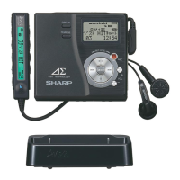
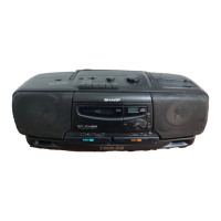
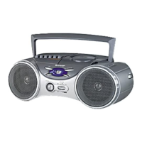
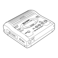
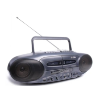
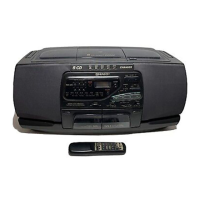
Identification and labeling of various parts of the device.

Disc Operation Procedures

Loading and Playing a Disc

Step-by-step instructions for inserting and playing a compact disc.

APSS Auto Program Search System

Using the Auto Program Search System to locate track beginnings.

Random Play Function

How to enable and control random playback mode.

Advanced Disc Operations

APMS Programmable Music Selector

Using the Automatic Programmable Music Selector feature.

Repeat Play Modes

Controlling repeat playback modes.

Transportation Lock

Procedure for securing the optical pickup during transport.

Disassembly and Component Replacement

Disassembly Instructions

Procedures for safely taking apart the unit for servicing.

Pickup Replacement

Steps for replacing the laser pickup assembly.

Disc Holder Fitting

Procedure for fitting the disc holder.

Troubleshooting Guide

Troubleshooting Flowcharts

Diagnostic flowcharts to identify and resolve operational issues.

Error Code Reference

List and explanation of system and operating error codes.

Service Loop

Service Loop Flowchart

A diagnostic loop for checking unit functions during service.

Technical Descriptions

Circuit Description

Explanation of key circuit operations, like spin motor control.

Adjustment Procedures

Laser Power Adjustment

Steps for calibrating the laser power output.

Focus Offset Adjustment

Steps for calibrating the focus offset.

Technical Reference

Schematic Diagram Notes

Important notes regarding the interpretation of schematic diagrams.

IC1 Function Table

IC1 VHITDA8808;-1 Function Table

Pin assignments and functions for IC1.

IC2 Function Table

IC2 VHITDA8809;-1 Function Table

Pin assignments and functions for IC2.

IC4 Function Table

IC4 RH-iX1812 UFZZ Function Table

Pin assignments and functions for IC4.

IC301 Function Table

IC301 VHIPC8576;-1 Function Table

Pin assignments and functions for IC301.

IC5 Function Table

IC5 VHISAA7310;-1 Function Table

Pin assignments and functions for IC5.

IC7 Function Table

IC7 VHITDA1543;-1 Function Table

Pin assignments and functions for IC7.

Packing Method (DX-361 EM Only)

Packing Procedures and Parts List

Instructions for packing the unit for shipping or storage.

Replacement Parts List

Integrated Circuits and Diodes

List of replacement ICs and diodes with part numbers.

Transistors

List of replacement transistors with part numbers.

Replacement Parts List

Capacitors

List of replacement capacitors with part numbers and values.

Resistors

List of replacement resistors with part numbers and values.

Replacement Parts List

Other Circuitry Parts and Cabinet Parts

Lists for miscellaneous circuitry parts and cabinet components.

Replacement Parts List

Accessories and Packing Parts

List of accessories and packing materials.

Service Information

Supply Voltage Setting

Instructions for setting the unit to operate on 110V or 220V.

Related product manuals