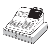
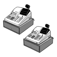
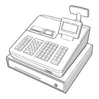
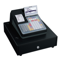
ER-A410/ER-A420 HARDWARE DESCRIPTION
– 9 –
POWER SUPPLY/CONTROL PINS
4. PRINTER CONTROL
The PR-45M printer is used.
4-1. STEPPING MOTOR CONTROL
The stepping motor is driven at a constant voltage by Sanken STA471A.
1step: 0.125mm, 1dot: 1step
Printing speed: 50mm/s
<CPU’s PORT>
<DRIVING STEP>
RECEIPT MOTOR
*When the motor is at rest, the same phase as the final excitation
phase is RUSH energized for 10 ms to turn off all phases.
3 Turn all AS~RDS and JAS~JDS into L.
No energizing should be allowed at least 30 ms after stopping the
motor before restarting.
When starting the motor, the first excitation phase is RUSH energized
for 10 ms to start the motor by acceleration control.
P96 1 O P96 LCDON L Out L LCD POWER ON
P97 100 I P97 IPLON In IPL ON SIGNAL
P100 97 I AN0 TM In
HEAD TEMPERA-
TURE MONITOR
P101 95 I AN1 VPTEST In HEAD VOLT-
AGE MONITOR
P102 94 I AN2 VREF In REFERENCE
VOLTAGE
P103 93 O AN3 /STRB1 H In
PRINTER STORE
SIGNAL 1
P104 92 O AN4 /STRB2 H In
PRINTER STORE
SIGNAL 2
P105 91 O P105 /STRB3 H In
PRINTER STORE
SIGNAL 3
P106 90 O P106 /STRB4 H In
PRINTER STORE
SIGNAL 4
P107 89 O P107 LATCH L In PRINTER
LATCH SIGNAL
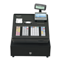
PORT PIN No. I/O PIN NAME FUNCTION
BYTE 8 I BYTE Connected to VDD
CNVSS 9 I CNVSS Connected to GND
/RESET 12 I /RESET
XOUT 13 O XOUT OPEN
VSS 14 VSS Connected to GND
XIN 15 I XIN Connected to Spectram
VCC 16 VCC Connected to VDD
VCC 62 VCC Connected to VDD
VSS 64 VSS Connected to GND
AVSS 96 AVSS Connected to GND
VREF 98 VREF Connected to VDD
AVCC 99 AVCC Connected to VDD
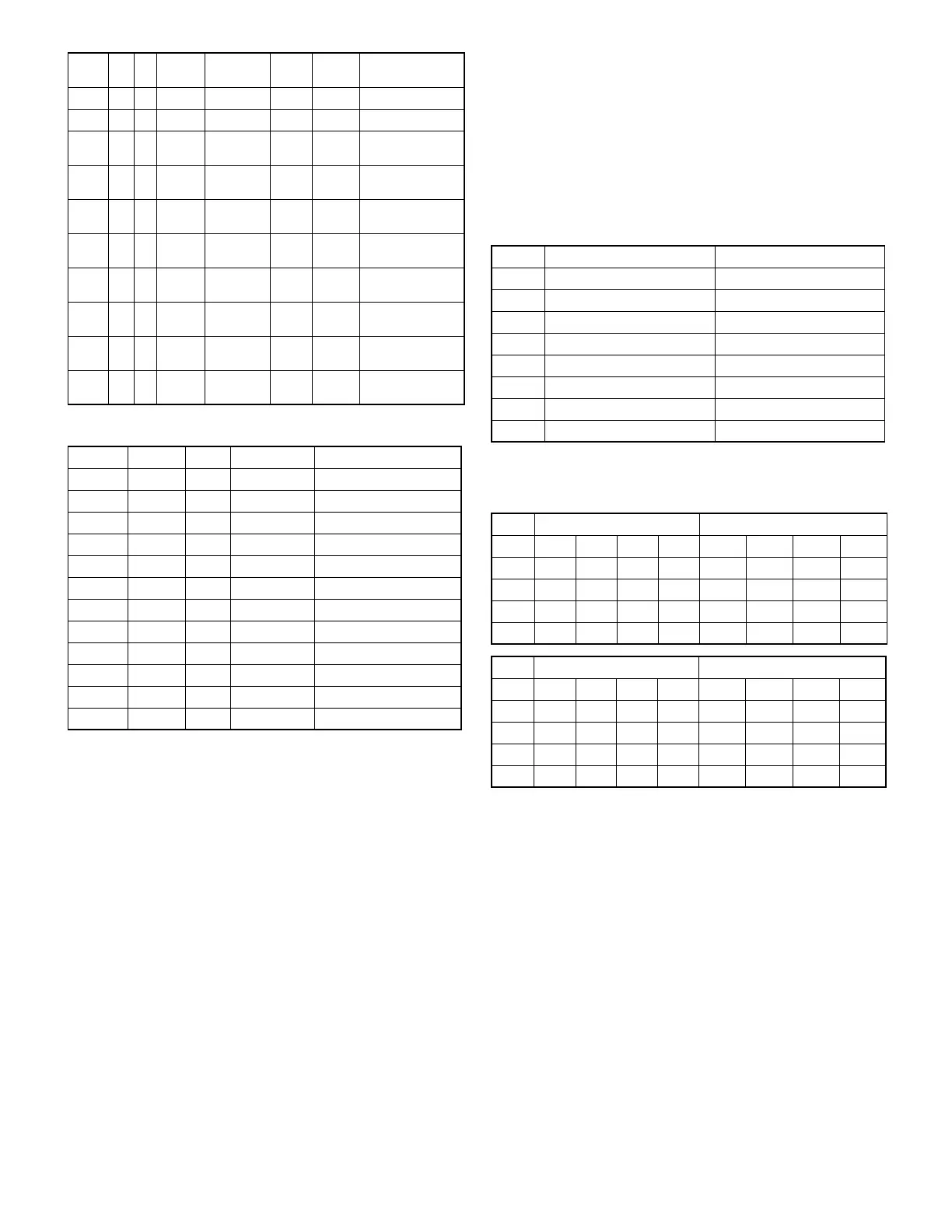
PORT
PIN
No.
I/O
Pin
name
Signal
name
Initial
value
OFF
MODE
Function
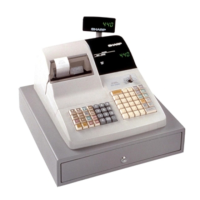
No. CPU PORT Signal to be used
80 P10 RAS
79 P11 RBS
78 P12 RCS
77 P13 RDS
76 P14 JAS
75 P15 JBS
74 P16 JCS
73 P17 JDS
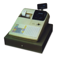
Driver IC input (CPU output) Motor drive signal
STEP RAS RBS RCS RDS /RPFA /RPFB /RPFC /RPFD
1HLLH L H H L
2LHLHH L H L
3LHHLH L L H
4HLHL L H L H
Driver IC input (CPU output) Motor drive signal
STEP JAS JBS JCS JDS /JPFA /JPFB /JPFC /JPFD
1LHHLH L L H
2LHLHH L H L
3HLLHL H H L
4HLHL L H L H