ER-A410/ER-A420 HARDWARE DESCRIPTION
– 12 –
6-3. OTHERS
The MODE key switch and other sensor signals are read with the CPU
port P90 and 91 at the keyboard strobe timing. Reading is performed
10~100us before turning off the strobe signal.
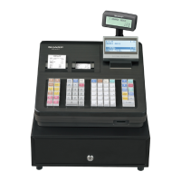
6-4. DISPLAY
The ER-A410/A420 is provided with the front LCD of 5 x 7dot, 2 lines 16
digits, and the 7-digit LED on the pop up side.
FRONT:
POP UP:
• DISPLAY DIGIT SIGNAL
The above ST0~ST6 are DIGIT signals.
ST0: 1st digit~ST6:7th digit
• DISPLAY SEGMENT SIGNAL (REFER TO 6-2.)
By writing segment data to 4000h, the LED segment signal can be
outputted.
DATA~SEGMENT correspondence
7. EFT I/F
The ER-A410/A420 can be connected with the EFT I/F PWB as an
option.
The EFT I/F is mapped in the /CS3 area.
By inserting the EFT PWB, the RS-232 CH2 signal is switched to the
signal from the EFT.
Since, however, the reception data (RTX) of RS232 CH2 is inputted to
the CPU without being cut, the CPU port must be set so that the input
can be received without problems. The EFT PWB unit is common
except for the EFT section of the ER-01EF and the I/O address from the
HOST.
7-1. EFT I/F
X: Not fixed (EFT 3 ECR just before)
1 Data read of SUB CPU 1: Not reading 0: Reading
2 Data to SUB CPU 1: YES 0: NO
3 Data to HOST CPU 1: YES 0: NO
EFT RESET
RESET signal to initialize the EFT I/F.
After resetting the machine, /EFTRST is outputted at LOW for more
than 10µsec.
During LOW period, the EFT I/F should not be accessed.
EFT CONNECT SIGNAL
EFT I/F connect signal 0: EFT PWB provided 1: EFT PWB not provided
CPU STO ST1 ST2 ST3 ST4 ST5 ST6 ST7 ST8 ST9
MODE P90 SRV PGM VOID OP X/Z REG MGR X1/Z1 X2/Z2 Key Select
OTHERS P91 PF-R PF-J RPE HEAD UP JPE DRAWER
OPEN
RS1_CI
P90 ST0 : MODE Key SRV “0” SRV mode
ST1 : MODE Key PGM “0” PGM mode
ST2 : MODE Key VOID “0” VOID mode
ST3 : MODE Key OP X/Z “0” OP X/Z mode
ST4 : MODE Key REG “0” REG mode
ST5 : MODE Key MGR “0” MGR mode
ST6 : MODE Key X1/Z1 “0” X1/Z1 mode
ST7 : MODE Key X2/Z2 “0” X2/Z2 mode
ST9 : Keyboard select “0” Flat key
“1” Normal key
P91 ST0 : Receipt feed “0” Receipt feed
ST1 : Journal feed “0” Journal feed
ST2 : Receipt paper end “1” Receipt paper end
ST3 : Head up “0” Head up
ST4 : Journal paper end “1” Journal paper end
ST6 : Drawer open sensor “0” Drawer open
ST9 : RS-232 ch1 CI signal
D0~D6 3 a~g
D7 3 DP
HOST CPU
I/O address
Name
0400EH DTR Used for data send/receive to/from
the EFT I/F CPU.
(Data register) When WRITE: ECR 3 EFT
When READ: EFT 3 ECR
READ/WRITE should be per-
formed only when the condition of
NOTE 1 is satisfied.
0400FH STR Used for data send/receive to/from
the EFT I/F CPU.
(Status register) When WRITE: Indicates the EFT I/F
status.
When READ: EFT sub system reset
control
D7 D6 D5 D4 D3 D2 D1 D0
XXXXXCLMIBFOBF
123
NOTE 1) Data write to DTR is performed when “CLM:1/IBF:0.”
Data read from DTR is performed when “OBF:1.”
Pin No. CPU PORT Signal to be used
33 P65 /EFTRST
Pin No. CPU PORT Signal to be used
19 P83 /EFTC