GENERAL ALIGNMENT
INSTRUCTION
Should it become necessary at any time to check the align-
ment of this receiver, proceed as follows;
1. Set the volume control (VR103) to maximum.
2. Attenuate the signals from the generator enough to swing
the most sensitive range of the output meter.
3. Use a non-metallic alignment tool.
4. Repeat adjustments to insure good results.
5. Set the
Function
Selector
Switch
(SW101)
to
"radio"
position.
AM
IF/RF
ALIGNMENT
• Set the signal generator to produce a signal of 400Hz, 30%,
AM modulated. ____
• For adjustments in steps 4 and 9, see
[Note
A|.
STEP
BAND
TEST
STAGE
FRE-
QUEN-
CY
DIAL
SETT-
ING
ADJUST-
MENT
REMARKS
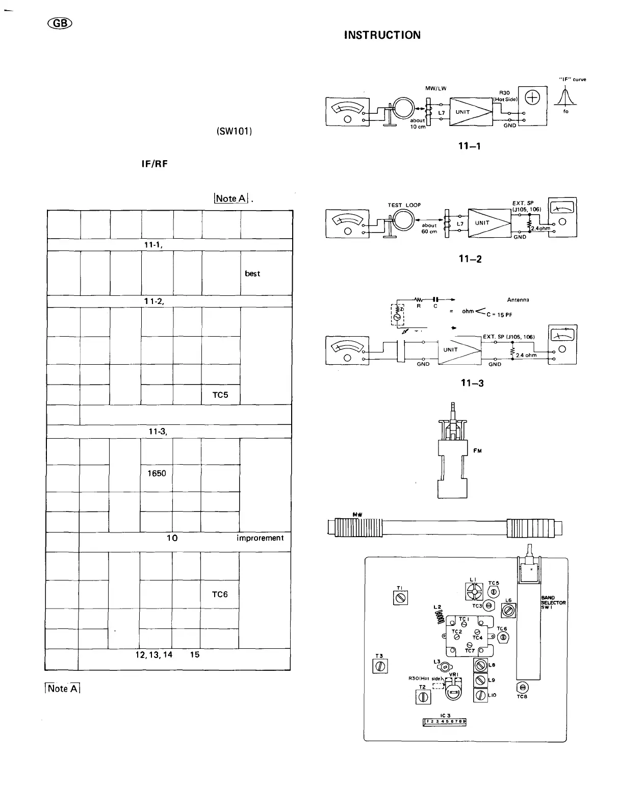
IF (As shown in Figure
11-1,
make connection of instrument.)
1
MW
IF
(H/HB):
455kHz
(E):
468
kHz
High
end of
dial
T3
Adjust for
best "IF"
curve
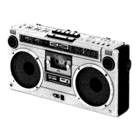
RF (As shown in Figure
1
1-2,
make connection of instrument.)
2
3
4
5
6
LW
LW
LW
LW
Band
cover-
age
Track-
ing
145kHz
295kHz
170kHz
270kHz
Low
end of
dial
High
end of
dial
170k
Hz
270k
Hz
L10
TC8
L7
TC5
Adjust for
maximum
output
Repeat steps 2,3,4 and 5 until no further improvement
can be made.
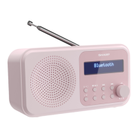
RF (As shown in Figure
11-3,
make connection of instrument.)
7
8
g
10
11
12
13
14
15
16
MW
MW
MW
MW
Band
cover-
age
Track-
ing
510kHz
1650
kHz
600
kHz
1400
kHz
Low
end of
dial
High
end of
dial
600
kHz
1400
kHz
L9
TC7
L7
TC4
Adjust for
maximum
output
Repeat
steps
7,8,9
and
1
0
until
no
further
improrement
can be made.
SW
SW
SW
SW
Band
cover-
age
Track-
ing
5.85
MHz
18.5
MHz
6.5
MHz
16
MHz
Low
end of
dial
High
end of
dial
6.5
MHz
16
MHz
L8
TC6
L6
TC3
Adjust for
maximum
output
Repeat steps
12,
13,
14
and
15
until no further impro-
vement can be made.
[Note
A|
Check the alignment of the receiver antenna coil by
bringing a piece of ferrite (such as a coil slug) near the antenna
loop
stick,
then
a
piece
of
brass.
If
ferrite
increases
output,
loop
requires
more
inductance.
If
brass
increases
output,
loop
requires less inductance. Change loop inductance by sliding the
bobbin toward the center of ferrite core to increase inductan-
ce, or away to decrease inductance.
SWEEP
GENERATOR
MW/LW
TEST LOOP BAR ANTENNA
OSCILLOSCOPE
SIGNAL
GENERATOR
Figure
11—1
MW/LW
BAR ANTENNA
ELECTRONIC
VOLTMETER
Figure
11—2
SIGNAL
GENERATOR
To Telescopic Rod
Antenna
R = 30 ohm
C-15PF
ELECTRONIC
Z: Output impedance of signal generator VOLTMETER
Z
«
50 ohnr
—y————
»
To chassis GND
tr
Telescopic Rod
DUMMY
Antenna
————
Figure
11—3
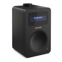
SWI01
FM
MODE
SELECTOR
M
1
*
L7
LW
Figure 11-4
-11-