FM
IF/RF
ALIGNEMIMT
• Set the signal generator to produce a signal of 400Hz, 30%,
FM modulated.
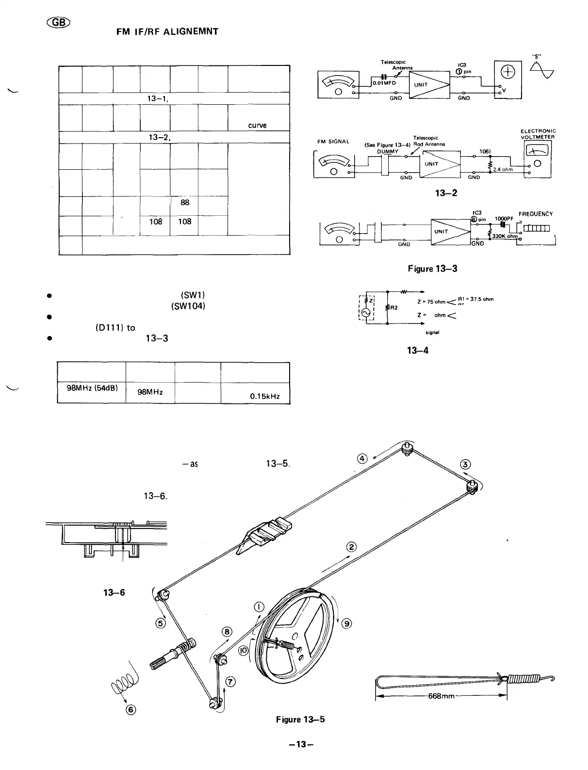
STEP
BAND
TEST
STA-
GE
FRE-
QUEN-
CY
DIAL
SET-
TING
AD-
JUST-
MENT
REMARKS
IF(As shown in Figure
13—1,
make connection of instrument.)
1
FM
IF
10.7
MHz
High
end of
dial
T1
T2
Adjust for
best "S"
curve
RF(As shown in Figure
13—2,
make connection of instrument.)
2
3
4
5
6
FM
FM
FM
FM
Band
cover-
age
Track-
ing
87.3
MHz
108.3
MHz
88
MHz
108
MHz
Low
end of
dial
High
end of
dial
Гв8
MHz
108
MHz
L3
TC2
L2
TC1
Adjust for
maximum
output
Repeat steps 2,3,4 and 5 until no further improvement
can be made.
FM STEREO ALIGNEMNT
Set the Band Selector Switch
(SW1)
to "FM" position and
FM Mode Selector Switch
(SW104)
to "stereo" position.
Before this adjustment, connect the anode side of Stereo
Indicator
(D111)
to
GND.
As shown in Figures
13-3
and 13-4, make connection of
instrument.
FREQUENCY
98MHz(54dB)
un modulated
DIAL
POINTER
98MHz
ADJUST-
MENT
VR1
REMARKS
Adjust for
38 ± 0.15kHz
10.7 MHz, Telescopic
FM SWEEP GENERATOR Rod
Antenna
OSCILLOSCOPE
"S"
curve
Figure 13-1
-——
,^,3-,^,
EXT. SP
(J105.
1061
Figure
13—2
FM STEREO
SIGNAL GENERATOR Telescopic
————————— Rod Antenna
(See Figure 13-4)
DUMMY
IC3
FREQUENCY
©pinlOpOPF
COUNTER
^rVL
шзш
I
_
0
__j330K_ohm
()
GND
t_—————___I
Figure
13—3
;]R2
R1
~W———»•
To Telescopic Rod Antenna
Z-75ohm<-
R1
-
375
°
hm
^~
R2
•
75
ohm
•R1 = 50 ohm
R2 - 50 ohm
Z-
50
ohm.
——————••
To Chassis GND
Z: Output impedance of
signal
generator
Figure
13-4
FM DUMMY
DIAL CORD STRINGING
1) Turn the drum fully clockwise and stretch its cord cover
the parts in the numerical order
—as
shown in Figure
13—5.
2) Turn the tuning control shaft fully counterclockwise, and
fix it with the pointer aligned with the zero (0) point on
the frame. See Figure
13—6.
"0" Point
Figure
13-6
4 turn