GX-CH170X/CH170Z
SW1 BAND [GX-CH170Z ONLY] FM—SW2—SW1
—MW
SW4 PICKUP IN ON—OFF
SW201 RECODE/PLAYBACK R—P
SW251 DUBBING SPEED/BEAT CANCEL NORMAL A—
NORMAL B—
HIGH C/A—B—C
SW253 BAND [GX-CH170X] FM—AM
SW253 TAPE SELECTOR/FM MODE NORMAL—CrO2/
[GX-CH170Z] FM STEREO—
FM MONO
SW601 TAPE 1 MAIN ON—OFF
SW602 TAPE 2 MAIN ON—OFF
SW603 TAPE1/2 SELECTOR ON—OFF
SW651 FUNCTION/REMOTO CONTROL CD—TUNER—
TAPE—OFF/
ON—OFF
SW701 POWER ON—OFF
– 16 –
NOTES ON SCHEMATIC DIAGRAM
1. Tuner
( ): AM mode
Marking except for ( ): FM mode
2. CD
( ): Play mode
Marking except for ( ): Stop state
3. Deck section
( ): Record mode
Marking except for ( ): Playback mode
Display / Control section:
( ): Active state
Marking except for ( ): CD Function mode at stop state
• Schematic diagram and Wiring Side of P.W.Board for this
model are subject to change for improvement without prior
notice.
• Parts marked with “ ” ( ) are important for
maintaining the safety of the set. Be sure to replace these
parts with specified ones for maintaining the safety and
performance of the set.
• Resistor:
To differentiate the units of resistors, the symbol as K and M
are used: the symbol K means 1000 ohm and the symbol M
means 1000 kohm and the resistor without any symbol is an
ohm resistor. The resistor designated "Fusible" is a fuse type
resistor
• Capacitor:
To indicate the unit of capacitor, a symbol P is used: this
symbol P means micro-micro-farad and the unit of the capacitor
without such a symbol is microfarad. As to electrolytic capacitor,
the expression “capacitance/withstand voltage” is used.
(CH), (TH), (RH), (UJ): Temperature compensation
(ML): Mylar type
(P.P.): Polypropylene type
• The indicated voltage in each section is the one measured by
Digital Multimeter between such a section and the chassis
with no signal given.
REF. NO DESCRIPTION POSITION
SW702 CD-STOP ON—OFF
SW703 CD-PLAY ON—OFF
SW704 CD-PAUSE ON—OFF
SW705 CD-CUE ON—OFF
SW706 CD-REVIEW ON—OFF
SW707 CD-DISC 1-2 ON—OFF
SW708 CD-RANDOM ON—OFF
SW709 VOLUME UP ON—OFF
SW710 VOLUME DOWN ON—OFF
SW711 CD-PROGRAM ON—OFF
SW712 CD-CLEAR ON—OFF
SW713 CD-TRAY1 OPEN/CLOSE ON—OFF
SW714 CD-TRAY2 OPEN/CLOSE ON—OFF
SW981 TRAY/MECHANISM UP ON—OFF
SW982 TRAY1 1a—1b
SW983 TRAY2 2a—2b
REF. NO DESCRIPTION POSITION
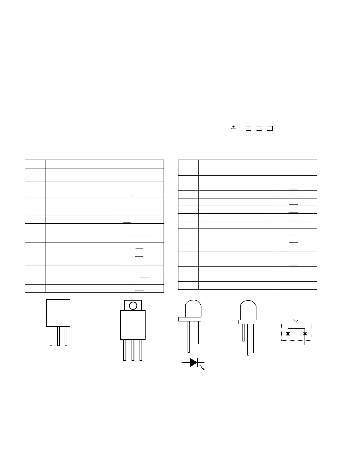
Figure 16 TYPES OF TRANSISTOR AND LED
ECB
(S)(G)(D)
(1) (2) (3)
FRONT
VIEW
BCE
FRONT
VIEW
2SC2001 K
2SB561 C
2SB562 C
2SD468 C
KRA102 M
KRC102 M
KTA1266 GR
KTC3199 GR
2SD2394 F
FRONT
VIEW
FRONT
VIEW
2
3
GREEN
1
RED
3N8PGN33
3N4PDN32
3N4GDN32