GX-CH170X/CH170Z
1 P03 MTCONT2 Output Changer mechanism motor control output No.2.
2 P10 POWER IN Input Power key input.
3 D0 POWER ON Output "L" when power is turned on.
4 P12 DATA(VOL) Output Electronic volume data.
5 P13 STB(VOL) Output Volume change after data fetching.
6 P11 CK(VOL) Output Electronic volume data fetch timing signal.
7 D1 MUTE Output System mute signal output.
For audio signal muting
8 D2 SYNC OUT Output Deck motor control output. "H" when REC is required for CD function.
9 D3 RES Output Reset output.
10 D4 CQCK Output Serial data sync clock for interface.
11 D5 COIN Output Servo control signal processing IC command output.
12 D6/CNTR0 RWC Output READ/WRITE control output. (from microcomputer)
13 D7/CNTR1 SL+ Output Slide motor feed output.
14 D8/INT0/ZEROX SL- Output Slide motor return output. SL+/SL- combination control. Track count monitor
15* D9/SCK/RTP0 SRS2 Output Surround control output 2.
16* D10/SOUT/ SRS1 Output Surround control output 1. Surround control with SRS1 and 2.
RTP1/PWM However, since Surround has three positions, "H, H" is not used.
17 P20/SIN DRF Intput HF level detection input.
18 P21/INT1 SQOUT Input Sub-code Q data input.
19 P22 WRQ Input Detection input for sub-Q code output standby.
Disc deceleration signal monitor. Track count monitor.
20 P23 PU IN Input CD pickup position detection. Innermost periphery: "L"
21 RESET RESET Input If "L" state is held for more than 0.75 usec (one machine cycle), reset state isset
(in case of 4 MHz oscillation).
22 X IN X IN Input Main clock input.
23 X OUT X OUT Output Main clock output.
24 VSS D GND — Power terminal GND (0V)
25 VDD D +5V — Power terminal +5V
26 XCOUT SU CLOUT Output Sub-clock output.
27 XCIN SU CLIN Input Sub-clock input
28 AVSS ADGND — A/D converter reference voltage GND terminal (0V is applied)
29 VREF AD +5V — A/D converter reference voltage input terminal.
Applied voltage must be not lower than 2V but not higher than VDD.
30 SEG26/P30/ REMOCON Input Remote control signal input.
INT2/AIN0 To be detected at fall edge.
31 SEG25/P31/AIN1 AC/DC Input AC/DC discrimination port. AC: "L" DC: "H"
32 SEG24/P32/AIN2 CD FUNC/ Input Function/REC detection.
SYNC-IN
33 SEG23/P33/AIN3 KEY1 Input Operation key input No.1.
34 SEG22/P40/AIN4 KEY2 Input Operation key input No.2.
35 SEG21/P41/AIN5 MODEL Input Model discrimination when power is turned on.
36 SEG20/P42/AIN6 TRAY SW Input Changer mechanism switch input. 5-position analog input.
37 SEG19/P43/AIN7 UP/LID SW Input Open TOP type: LID SW port. Changer type: Mechanism UP SW port.
38 VLC3 VLC3 Input LCD bias setting power terminal.
39 SEG18/VLC2 VLC2 Input Internal divided resistor is connected. 1/3 bias, 1/4 duty
40 SEG17/VLC1 VLC1 Input Internal divided resistor is connected.
41-44 COM3-COM0 COM3-COM0 Output LCD control common terminal (1/4 duty).
45-61 SEG16-SEG0 SEG16-SEG0 Output LCD control segment terminal.
(45*-52*)
62 P00 TR1 LED Output For CD changer validity indication. For output tray No.1.
63 P01 TR2 LED Output For CD changer validity indication. For output tray No.2.
64 P02 MTCONT1 Output Changer mechanism motor control output No.1.
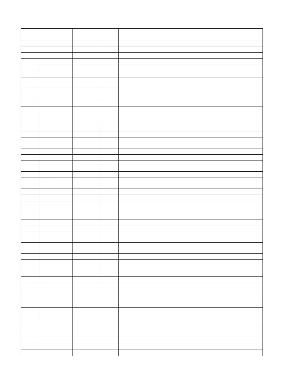
FUNCTION TABLE OF IC
IC901 RH-iX0146AWZZ (IX0146AW): System Control Microcomputer
– 36 –
Port Name Input/
Output
Terminal
Name
Pin No. Function
In this unit, the terminal with asterisk mark (*) is (open) terminal which is not connected to the outside.