••
•
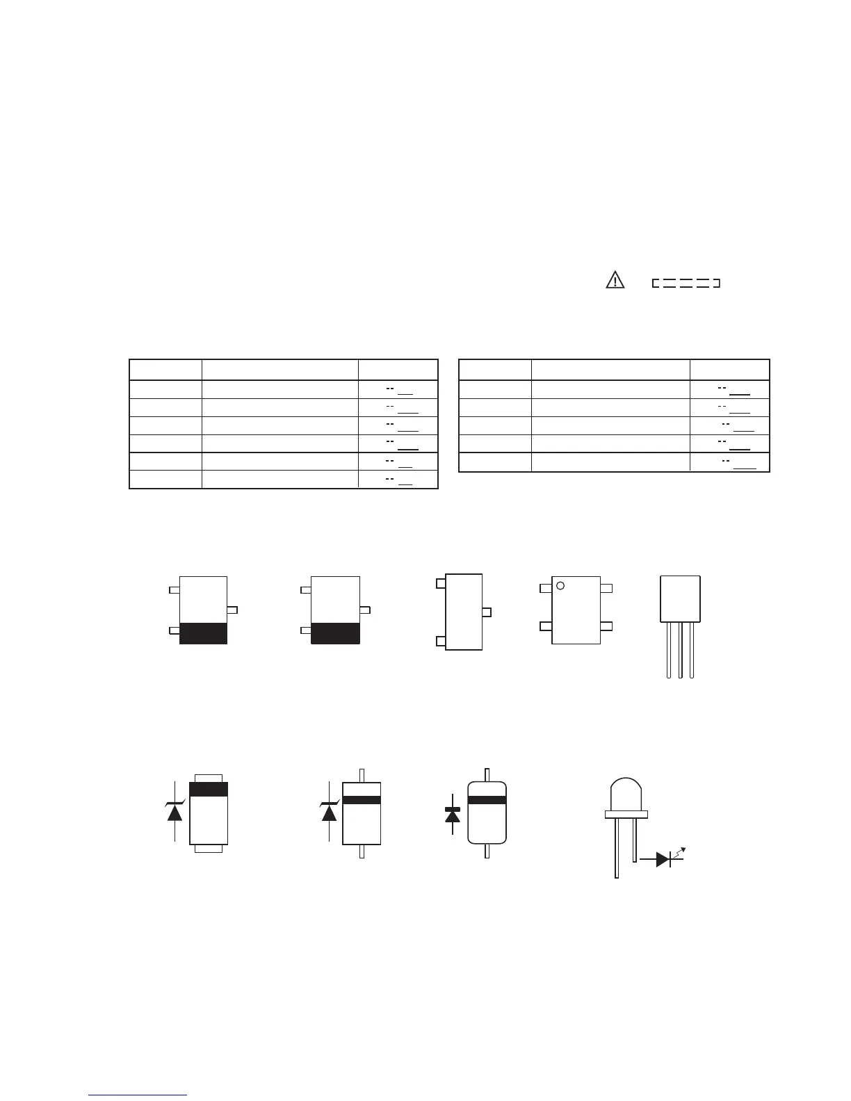
Resistor:
To differentiate the units of resistors, such symbol as
K and M are used: the symbol K means 1000 ohm
and the symbol M means 1000 kohm and the
resistor without any symbol is ohm-type resistor.
Besides, the one with “Fusible” is a fuse type.
Capacitor:
To indicate the unit of capacitor, a symbol P is used:
this symbol P means pico-farad and the unit of the
capacitor without such a symbol is microfarad. As to
electrolytic capacitor, the expression “capacitance/
withstand voltage is used”.
(CH), (TH), (RH), (UJ): Temperature compensation
(ML): Mylar type
(P.P.): Polypropylene type
Schematic diagram and Wiring Side of P.W.Board
for this model are subject to change for
improvement without prior notice.
•
•
The indicated voltage in each section is the one
measured by Digital Multimeter between such a
section and the chassis with no signal given.
Parts marked with “ ” ( ) are
important for maintaining the safety of the set. Be
sure to replace these parts with specified ones for
maintaining the safety and performance of the set.
PWB Switch Location
REF. NO
SW700
SW701
SW702
TUNER/AUDIO IN
USB
iPod
CD
SW703
DEMO/DIMMER
SW704
SW705
X-BASS/EQ
ONON
ON OFF
ON
OFFON
ONON
ONON
OFF
POSITION ON.FERNOITPIRCSED
SW706
SW707
SW708
PRESET DOWN
PRESET UP
ON/STANDBY
VOLUME DOWN
SW709
VOLUME UP
SW710
ON OFF
VOL
OFFON
MIN
VOL
MAX
POSITIONDESCRIPTION
ON OFF
1. In the tuner section,
2. In the CD section, the CD is stopped.
indicates AM
indicates FM stereo