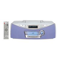
GX-M10
– 1
This document has been published to be used for
after sales service only.
The contents are subject to change without notice.
iPhone not included.
iPad, iPhone, iPod, iPod classic, iPod nano, and
iPod touch are trademarks of Apple Inc., registered
in the U.S. and other countries.
“Made for iPod,” “Made for iPhone,” and “Made for iPad”
mean that an electronic accessory has been designed to
connect specifically to iPod, iPhone, or iPad,
respectively, and has been certified by the developer to
meet Apple performance standards. Apple is not
responsible for the operation of this device or its
compliance with safety and regulatory standards. Please
note that the use of this a
ccessory with iPod, iPhone, or
iPad may affect wireless performance.
PRECAUTIONS FOR USING LEAD-FREE SOLDER
CHAPTER 1. GENERAL DESCRIPTION
[1] Important Service Safety Precaution ................. 1-1
[2] Important Service Notes (for U.S.A only)..... 1-1
[3] Specifications .................................................... 1-2
[4] Name Of Parts................................................... 1-3
CHAPTER 2. ADJUSTMENTS
[1] CD Section .................................................. 2-1
[2] Test Mode .................................................... 2-1
[3] Standard Specification Of Stereo System
Error Message Display Contents SYSTEM
PROTECT detection and AMP PROTECT
detection display ......................................... 2-1
CHAPTER 3. MECHANICAL DESCRIPTION
[1] Disassembly ................................................ 3-1
CHAPTER 4. CIRCUIT DESCRIPTION
[1] Waveform Of Servo Circuit .......................... 4-1
[2] Voltage......................................................... 4-2
CHAPTER 5. FLOWCHART
[1] Troubleshooting ........................................... 5-1
CHAPTER 6. MAJOR PART DRAWING
[1] Function Table of IC ..................................... 6-1
[2] LCD Display................................................. 6-5
CHAPTER 7. DIAGRAMS
[1] Main Block Diagram..................................... 7-1
CHAPTER 8. CIRCUIT SCHEMATICS AND PARTS
LAYOUT
[1] Notes On Schematic Diagram ..................... 8-1
[2] Type Of Transistor And LED ........................ 8-1
[3] Schematic Diagram ..................................... 8-2
[4] Chart Of Connecting Wires.......................... 8-7
[5] Wiring Side Of PWB .................................... 8-8
PARTS GUIDE