HT-DV40H
8 – 29
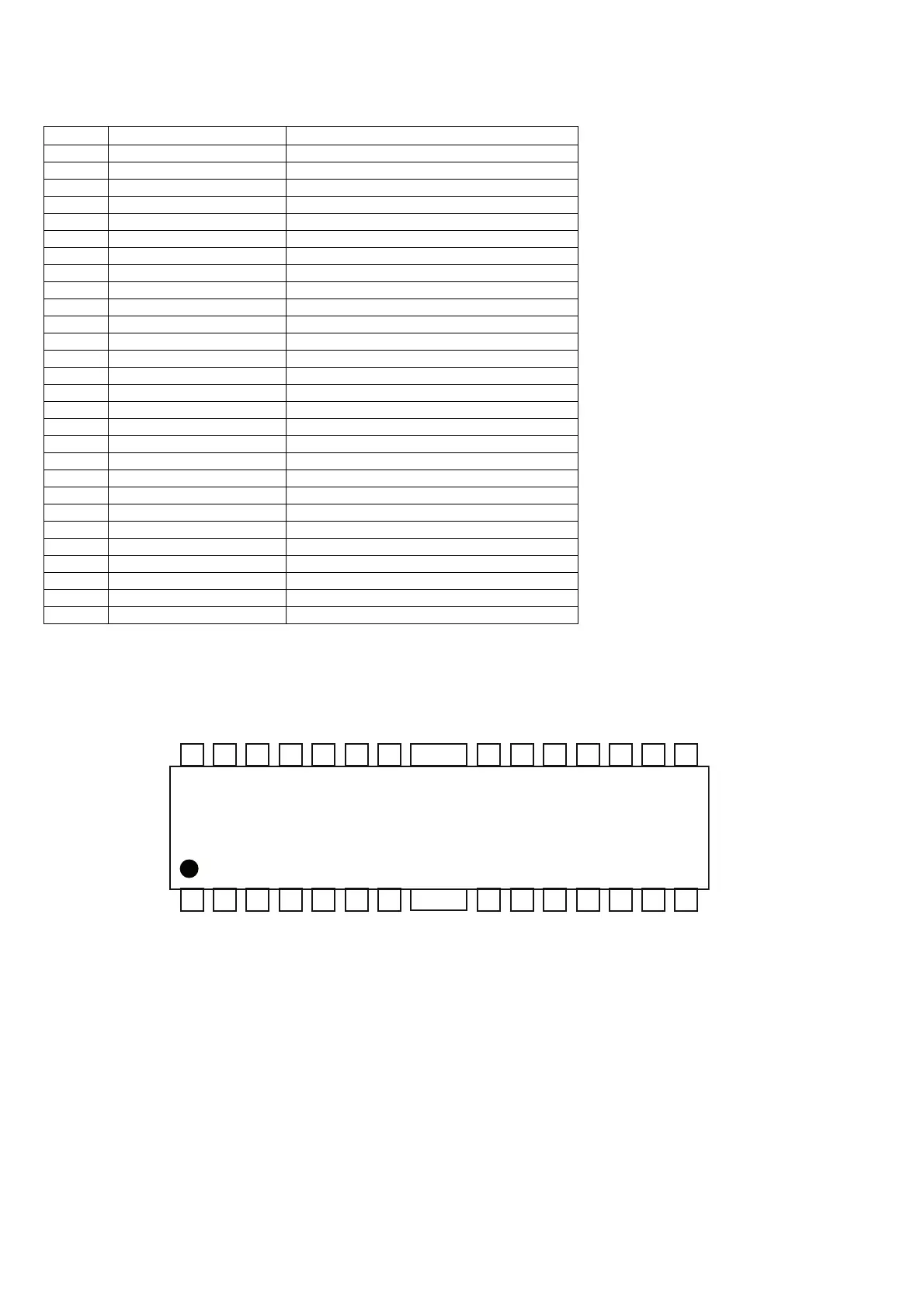
IC2 VHIAT5669H++1 : 5 CHANNEL MOTOR DRIVER (AT5669) (2/2 )
PIN DESCRIPTION
Notes: The indicated polarities for the output pins are under the condition that all inputs are (+).
The power supplies for the driver output are Vcc1 for the loader, Vcc2 for focus and tracking
drivers, and Vcc for pre-block and sled driver. Therefore, make sure Vcc1†Vcc2.
PIN CONFIGURATION
Pin No. Pin name Function
1 IN1 CH1(Focus coil) input
2 DL1 Linear Regulator 3V3 driver output
3 FB2 Linear Regulator 2 feedback input
4 IN2 CH2(Sled driver) input
5 3V3 Linear Regulator 3V3 input
6 FWD CH5 forward input
7 REV CH5 reverse input
8 VCC1 Power Supply 1
9 OUT5- CH5(Tray driver) output(-)
10 OUT5+ CH5(Tray driver) output(+)
11 OUT2+ CH2(Sled driver) output (+)
12 OUT2- CH2(Sled driver) output (-)
13 OUT1- CH1(Focus coil) output (-)
14 OUT1+ CH1(Focus coil) output (+)
15 OUT4+ CH4(Tracking coil) output (+)
16 OUT4- CH4(Tracking coil) output (-)
17 OUT3+ CH3(Spindle) output (+)
18 OUT3- CH3(Spindle) output (-)
19 VCC2 Power Supply 2
20 CPIP OP positive input
21 VCTL CH5 Speed control input
22 CPIN OP negative input
23 IN3 CH3(Spindle) input
24 CPO OP Output
25 DL2 Adjustable Linear Regulator driver output
26 IN4 CH4 (Tracking driver) input
27 VBIAS VREF input pin
28 MUTE_1_2_3_4 Mute control for CH1,CH2,CH3,CH4
AT5669
28 27 26 25 24 23 22 PGND 21 20 19 18 17 16 15
1 2 3 4 5 6 7 PGND 8 9 10 11 12 13 14