HT-SB200
6 – 1
CHAPTER 6. CIRCUIT SCHEMATICS AND PARTS LAYOUT
[1] Notes On Schematic Diagram
•Resistor:
To differentiate the units of resistors, such symbol as
K and M are used: the symbol K means 1000 ohm
and the symbol M means 1000 kohm and the
resistor without any symbol is ohm-type resistor.
Besides, the one with “Fusible” is a fuse type
• Capacitor:
To indicate the unit of capacitor, a symbol P is used:
this symbol P means pico-farad and the unit of the
capacitor without such a symbol is microfarad. As to
electrolytic capacitor, the expression “capacitance/
withstand voltage” is used.
(CH), (TH), (RH), (UJ): Temperature compensation
(ML): Mylar type
(P.P.): Polypropylene type
• Schematic diagram and Wiring Side of P.W.Board
for this model are subject to change for
improvement without prior notice.
• The indicated voltage in each section is the one
measured by Digital Multimeter between such a
section and the chassis with no signal given.
• Parts marked with “ ” are important for
maintaining the safety of the set. Be sure to replace
these parts with specified ones for maintaining the
safety and performance of the set.
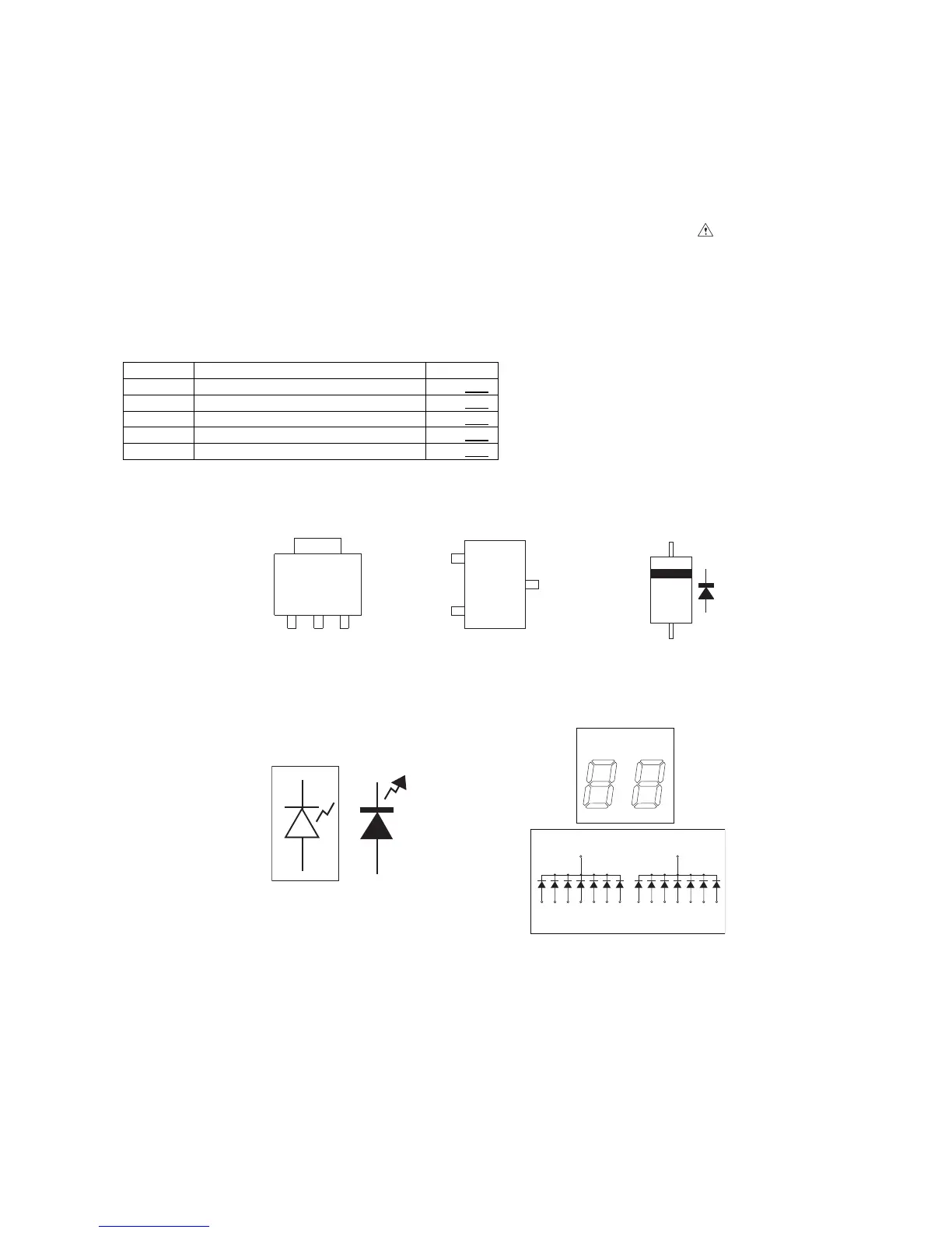
[2] Types Of Transistor And LED
REF. NO DESCRIPTION POSITION
SW701 POWER ON/STAND-BY ON—OFF
SW702 VOLUME DOWN ON—OFF
SW703 VOLUME UP ON—OFF
SW704 SURROUND ON—OFF
SW705 FUNCTION ON—OFF
KiA1117F
B(1) C(2) E(3)
TOP VIEW
TOP VIEW
MA111G
KDS226
KRC101S
KRC107S
KRA107S
KRC104S
B
(3)
E
(1)
C
(2)
TOP
VIEW
PCL194H
PCL165S
COM
DIG 1
DIG 1
DIG 2
DIG 2 DIG 2
4
COM
5
ABCDEFG
15 13 1 3 2 14 16
10 12 8 6 7 11 9
AB
CE
FB
G
D
A
CD EF G