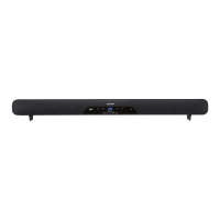
HT-SB200
3 – 1
CD-ES700/CD-ES77CD-ES700/CD-ES77Service ManualCD-ES700/CD-ES77MarketE
CHAPTER 3. MECHANISM BLOCKS
[1] Disassembly
Caution On Disassembly
Follow the below-mentioned notes when disassembling the unit and reassembling it, to keep it safe and ensure
excellent performance:
1. Be sure to remove the power supply plug from the wall outlet before starting to disassemble the unit.
2. Take off nylon bands or wire holders where they need to be removed when disassembling the unit. After servicing
the unit, be sure to rearrange the leads where they were before disassembling.
3. Check that all speaker cushions (refer items 212, 214, 215 and 216 on pages 6 and 7 of Parts Guide) are properly
sealed otherwise vibration noise will be very distinct at low frequency sound.
Replace the cushions if they are found damaged during servicing.
STEP REMOVAL PROCEDURE FIGURE
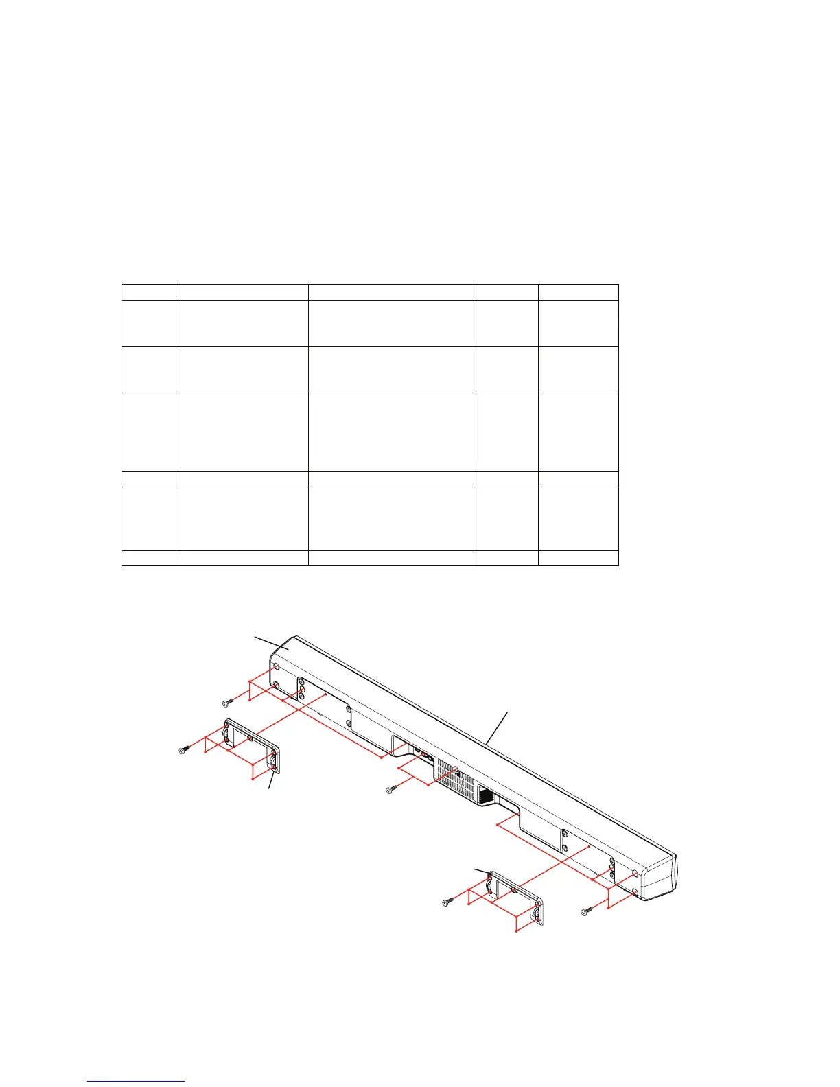
1 Back Cabinet Assy 1. Wall Mount Bracket…… (A1)x2 1
2. Screw…………..………. (A2)x10
3. Screw…………..………. (A3)x10
2 Amp PWB 1. Screw……….………….. (B1)x2 2
2. Connector…….……….. (B2)x1
3. Socket………………..… (B3)x2
3 Power PWB 1. Main Chassis……….…. (C1)x1 2
2. Screw………….…….…. (C2)x4
3. Screw………….…….…. (C3)x1
4. Socket………………..…
(C4)x1
5. Screw………………...…
(C5)x2
4 Main PWB 1. Screw………….………. (D1)x1 2
5 Woofer 1. Duct Port Holder…….… (E1)x2 3
2. Duct Port Assy………… (E2)x2 3
3. Screw………….…….…. (E3)x12 3
2. Screw………….………. (E4)x8 4
6 Speaker 1. Screw………….………. (F1)x8 4
Back Cabinet Ass’y
(A3)x4
M3x10mm
(A3)x2
M3x10mm
(A1)x1
Wall Mount Bracket
(A2)x5
M3.5x10mm
(A1)x1
Wall Mount Bracket
Front Cabinet Ass’y
(A2)x5
M3.5x10mm
(A3)x4
M3x10mm
Figure 1