EasyManua.ls Logo

Sharp LC-13SH3U User Manual

Sharp LC-13SH3U
67 pages
To Next Page IconTo Next Page
Page #1 background imageLoading...
Page #1 background image
LC-13AV6U
In the interests of user-safety (Required by safety regulations in some countries) the set should be restored
to its original condition and only parts identical to those specified should be used.
MODEL
LC-13AV6U
This document has been published to be used for
after sales service only.
The contents are subject to change without notice.
LCD COLOR TELEVISION
CONTENTS
» IMPORTANT SERVICE SAFETY PRECAUTION .........................................................................................2
» SPECIFICATIONS ........................................................................................................................................5
» OPERATION MANUAL .................................................................................................................................6
» DIMENSIONS ...............................................................................................................................................8
» REMOVING OF MAJOR PARTS ..................................................................................................................9
» ADJUSTING PROCEDURE OF EACH SECTION ..................................................................................... 13
» PUBLIC MODE SETTING PROCEDURE ..................................................................................................24
» TROUBLE SHOOTING TABLE ..................................................................................................................29
» MAJOR IC INFORMATIONS ......................................................................................................................32
» BLOCK DIAGRAM ......................................................................................................................................34
» OVERALL WIRING DIAGRAM ...................................................................................................................36
» DESCRIPTION OF SCHEMATIC DIAGRAM .............................................................................................38
» SCHEMATIC DIAGRAM
ËR/C, LED Unit ..........................................................................................................................................39
ËSUB Unit ..................................................................................................................................................40
ËMAIN Unit .................................................................................................................................................48
ËOPERATION Unit .....................................................................................................................................58
» PRINTED WIRING BOARD ASSEMBLIES ................................................................................................59
» REPLACEMENT PARTS LIST....................................................................................................................72
» PACKING OF THE SET ..............................................................................................................................83
Page
N46A3LC13AV6U
Question and Answer IconNeed help?

Do you have a question about the Sharp LC-13SH3U and is the answer not in the manual?

Sharp LC-13SH3U Specifications

General IconGeneral
Screen Size13 inches
Display TechnologyLCD
Aspect Ratio4:3
Brightness430 cd/m²
Response Time16 ms
HDMI Ports0
USB Ports0
InputsComposite, S-Video
Resolution640 x 480

Summary

Important Service Safety Precautions

General Safety Warnings

Essential safety warnings for technicians and users concerning modifications and power disconnection.

Receiver Safety Checks

Procedures to perform before returning the receiver to the user, focusing on fire and shock hazards.

Safety Notices

Information on safety-related components and the importance of using identical replacement parts.

Lead-Free Solder Precautions

Employing Lead-Free Solder

Guidance on the model's use of lead-free solder and its identification.

Using Lead-Free Solder

Best practices and recommendations for using lead-free wire solder.

Soldering Procedures

Techniques and precautions for successful lead-free soldering.

Product Specifications

Main Unit Operation

Main Unit Part Names

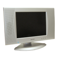
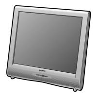
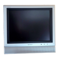
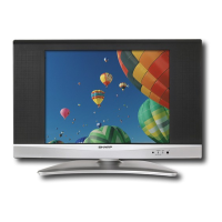
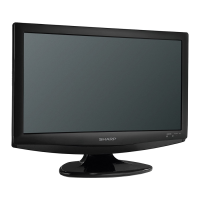
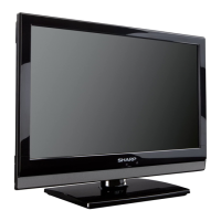
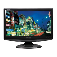
Identification of controls, terminals, and components on the main unit.

Indicators and Status

Explanation of power and sleep timer indicators on the main unit.

Operational Procedures

Instructions for headphone use and cable management.

Remote Control Operation

Remote Control Components

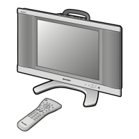
Identification of buttons and features on the remote control.

Battery Installation and Usage

Steps for installing batteries and guidelines for remote control usage.

Product Dimensions

Removing Major Parts

LCD Panel Handling Precautions

Side-B Service Precautions

Adjustment Procedures

Preparation Steps

Initial setup steps for calibrating the TV.

Accessing Adjustment Modes

Methods to enter the checker and adjustment process modes.

Key Operations in Adjustment

How to navigate menus and adjust settings during calibration.

Adjustment Test Patterns

Displaying Test Patterns

Procedure to display test patterns for screen adjustment.

Available Test Patterns

Overview of the 22 types of test patterns available for display.

Public Mode Settings

Starting Public Mode

Methods to access the public mode setup screen.

Password Entry

Procedure for entering the 3-digit password to verify public mode access.

Public Mode Setting Items

Maximum Volume Setting

Configuration options for the maximum adjustable volume.

Volume Fixed Setting

Options to fix or vary the sound volume output.

Volume Fixed Level

Setting the specific volume level when 'Volume Fixed' is selected.

Remote Control Button Settings

Configuration of remote control button functionality in public mode.

Troubleshooting Table

Major IC Information

IC2003 Pin Description

Detailed listing of pins and their functions for IC2003.

Block Diagram

Overall Wiring Diagram

Schematic Diagram Description

Voltage Measurement Conditions

Guidelines for measuring circuit voltages under specific conditions.

Resistor and Capacitor Notation

Explanation of symbols and notations used for resistors and capacitors.

General Safety Notes

Crucial safety warnings for schematic interpretation and component replacement.

R/C, LED Unit Schematic

Sub Unit Schematic (1/4)

Sub Unit Schematic (2/4)

Sub Unit Schematic (3/4)

Sub Unit Schematic (4/4)

Main Unit Schematic (1/5)

Main Unit Schematic (2/5)

Main Unit Schematic (3/5)

Main Unit Schematic (4/5)

Main Unit Schematic (5/5)

Operation Unit Schematic

Printed Wiring Board Layouts

Operation Unit - Wiring Side

PWB layout for the operation unit, showing wiring side components.

Operation Unit - Chip Parts Side

PWB layout for the operation unit, showing chip parts side components.

R/C, LED Unit - Wiring Side

PWB layout for the R/C, LED unit, showing wiring side components.

R/C, LED Unit - Chip Parts Side

PWB layout for the R/C, LED unit, showing chip parts side components.

Sub Unit - Wiring Side PWB Layout

Sub Unit - Chip Parts Side PWB Layout

Main Unit - Side-A PWB Layout

Main Unit - Chip Parts Side-A PWB Layout

Main Unit - Side-B PWB Layout

Main Unit - Chip Parts Side-B PWB Layout

Parts List

Ordering Replacement Parts

Instructions on how to order replacement parts, including required information.

Printed Wiring Board Assemblies

List of PWBs supplied as complete assemblies, not as individual parts.

Integrated Circuits

List of integrated circuits used in the unit, with part numbers and descriptions.

Transistors

List of transistors used in the unit, with part numbers and descriptions.

Diodes

List of diodes used in the unit, with part numbers and descriptions.

Crystals

List of crystals used in the unit, with part numbers and descriptions.

Cabinet and Mechanical Parts

Operation Unit Assembly

List of mechanical parts and their locations for the operation unit.

R/C, LED Unit Assembly

List of mechanical parts and their locations for the R/C, LED unit.

Sub Unit Assembly

List of mechanical parts and their locations for the sub unit.

Main Unit Assembly

List of mechanical parts and their locations for the main unit.

Supplied Accessories

Packing Parts

Service Jigs

Packing the Set

Related product manuals