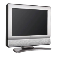
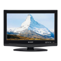
1. Put the Cabinet Back Ass'y on the bottom.
2. Short circuit the position shown in Fig. 1-4 using a 1. Put the Cabinet Back Ass'y on the bottom.
soldering iron. If you remove the DVD Deck with no 2. Remove the 2 screws (1).
soldering, the Laser may be damaged. 3.
Disconnect the followin
.
3. Disconnect the following connectors: 4. Remove the Tuner PCB in the direction of arrow (A).
CP2301, CP2302, CP2303, CP8501 and CP8502
Tuner in the direction of arrow
4. Remove the 3 screws (1). 6. Remove the 2 screws (2).
5. Remove the DVD DECK Ass'y in the direction of 7. Remove the Shield Digital Bottom Ass'y in the
arrow (A). direction of arrow (C).
6. Remove the 4 screws (2). 8. Remove the 7 screws (3).
7.
Unlock the 2 su
.
9. Disconnect the followin
connectors:
8.
Remove the DVD MT PCB in the direction of arrow
CP301, CP2201, CP3808, CP3809 and CP4301
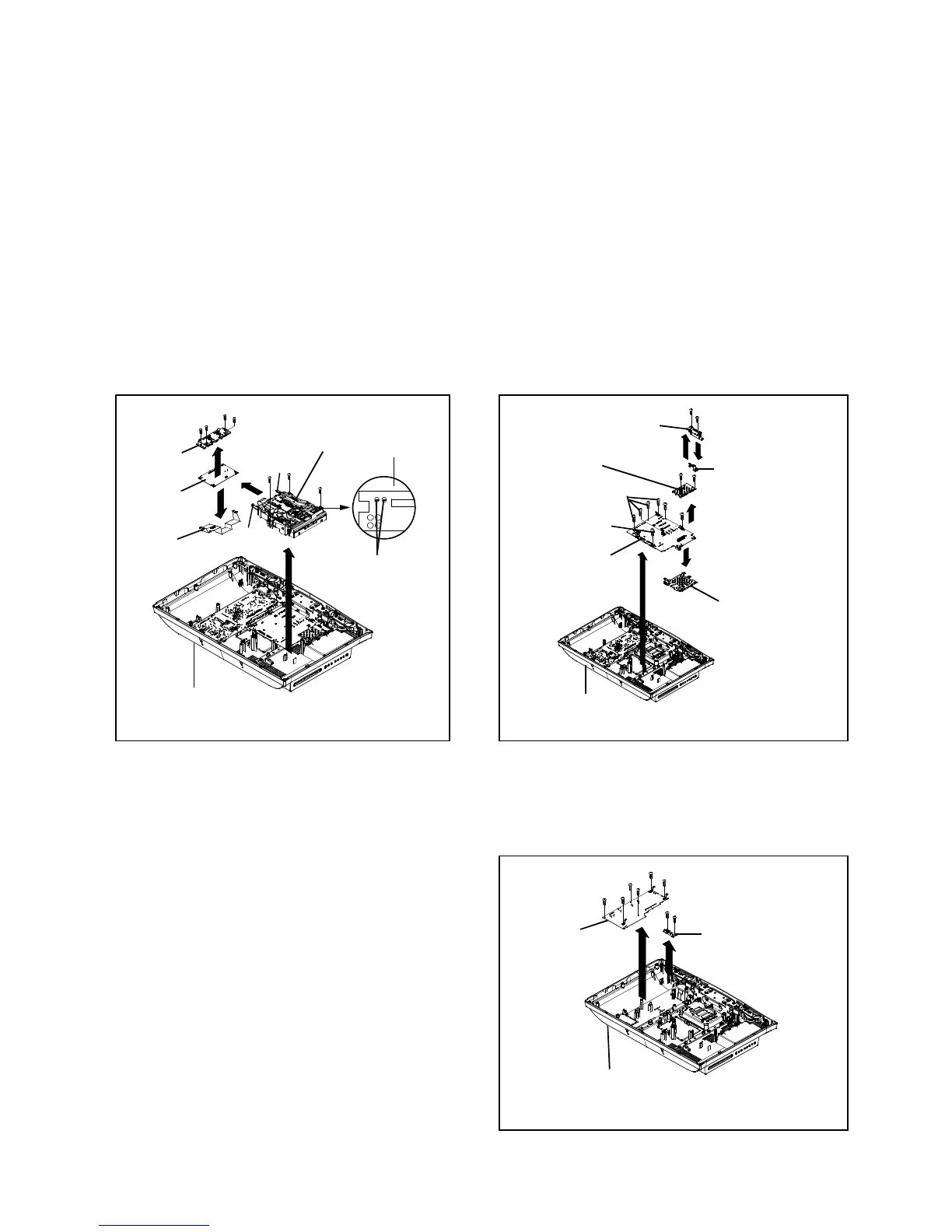
9. Remove the Shield LVDS in the direction of arrow (C). 10. Remove the Main PCB in the direction of arrow (D).
10. Remove the Shield LVDS Bottom in the direction of arrow (D). 11. Remove the Shield Digital-Top in the direction of arrow (E).
DISASSEMBLY INSTRUCTIONS
(1)
(B)
(3)
(2)
Shield LVDS
DVD Deck Ass'y
Pick Up PCB
(1)
(1)
Shield LVDS Bottom
(2)
(2)
(2)
DVD MT PCB
(3)
(C)
(D)
(1)
(2)
(1)
(B)
(2)
(C)
Shield Digital Bottom Ass'y
Tuner PCB
Spring Tuner
(3)
(3)
(3)
(3)
(A)
B1-2
NOTE 1-6: POWER PCB/REMOCON PCB
1. Before your operation, please read "PREPARATION 1. Remove the 2 screws (1).
OF SERVICING". 2. Remove the Remocon PCB in the direction of arrow (A).
2. Use the Lead Free solder. 3. Remove the 6 screws (2).
3. Manual soldering conditions 4. Remove the Power PCB in the direction of arrow (B).
•
Soldering temperature: 350 ± 5
• Soldering time: Within 4 seconds
• Soldering combination: Sn-3.0Ag-0.5Cu
4. When Soldering/Removing of solder, use the drawing
equipment over the Pick Up Unit to keep the Flux
smoke away from it.
5. When installing the DVD Deck, remove all the soldering
on the short circuit position after the connection of Pick
Up PCB and DVD MT PCB connector.
(A)
Back Cabi Ass'y
Short circuit using a
soldering iron.
Fig. 1-4
Back Cabi Ass'y
Fig. 1-5
Main PCB
(D)
Shield Digital-Top
Fig. 1-6
(2)
(1)
Power PCB
(A)
(2)
(B)
Back Cabi Ass'y
(2)
(2)
Remocon PCB
(2)
(2)
(1)
B1-2
 Loading...