In the interests of user-safety (Required by safety regulations in some countries) the set should be re-
stored to its original condition and only parts identical to those specified should be used.
MODEL
This document has been published to be used for
after sales service only.
The contents are subject to change without notice.
LCD COLOR TELEVISION
CONTENTS
ネ
IMPORTANT SERVICE SAFETY PRECAUTION ..........................................................................................2
ネ
SPECIFICATIONS .........................................................................................................................................5
ネ
OPERATION MANUAL ..................................................................................................................................7
ネ
DIMENSIONS ..............................................................................................................................................11
ネ
REMOVING OF MAJOR PARTS .................................................................................................................13
ネ
ADJUSTING PROCEDURE OF EACH SECTION ......................................................................................18
ネ
PUBLIC MODE SETTING PROCEDURE ...................................................................................................43
ネ
TROUBLESHOOTING TABLE .....................................................................................................................48
ネ
MAJOR IC INFORMATIONS .......................................................................................................................56
ネ
BLOCK DIAGRAM .......................................................................................................................................58
ネ
OVERALL WIRING DIAGRAM ....................................................................................................................60
ネ
DESCRIPTION OF SCHEMATIC DIAGRAM ..............................................................................................62
ネ
SCHEMATIC DIAGRAM
RC/LED Unit ..............................................................................................................................................63
MAIN Unit ..................................................................................................................................................64
SUB Unit ....................................................................................................................................................82
POWER_INVERTER Unit ..........................................................................................................................86
KEY Unit ....................................................................................................................................................88
ネ
PRINTED WIRING BOARD ASSEMBLIES .................................................................................................89
ネ
REPLACEMENT PARTS LIST ...................................................................................................................109
ネ
PACKING OF THE SET .............................................................................................................................126
Page
N87B1LC19K24U
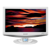
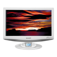
LC-19SK24U
LC-19SK24U-W
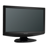
LC-19SB24U
LC-19SB24U-W
LC-19SB14U
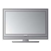
LC-19D44U