DISASSEMBLY INSTRUCTIONS
B1-2
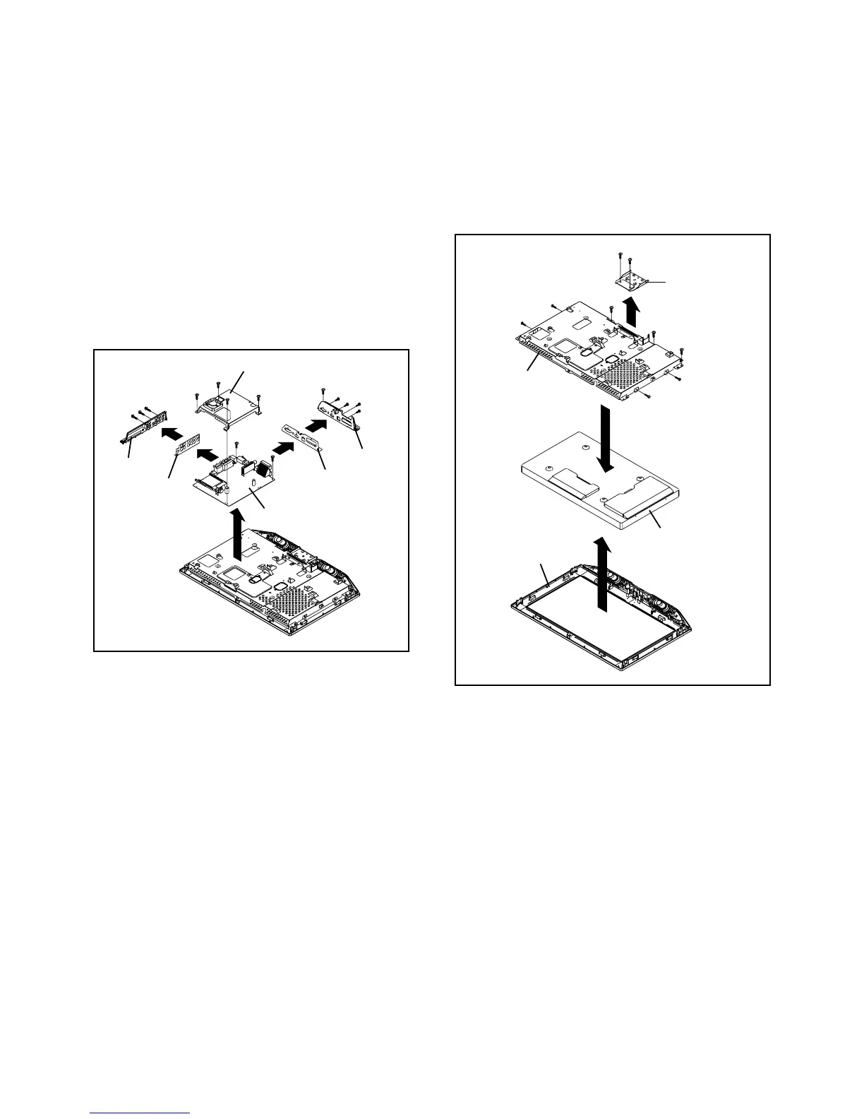
Fig. 1-5
1-5: MAIN PCB (Refer to Fig. 1-5)
1.
2.
3.
4.
5.
6.
7.
8.
9.
10.
11.
Disconnect the following connectors:
(CP6700, CP6701, CP6702, CP6703 and CP6705).
Remove the 6 screws 1.
Remove the screw 2.
Remove the Shield Digital and Main PCB in the direction
of arrow (A).
Remove the 3 screws 3.
Remove the Plate Jack Side in the direction of arrow (B).
Remove the Shield Jack Side in the direction of arrow
(C).
Remove the 3 screws 4.
Remove the screw 5.
Remove the Plate Jack in the direction of arrow (D).
Remove the Shield Jack in the direction of arrow (E).
1
Main PCB
(B)
(A)
1
1
1
1
1
Shield Digital
3
3
3
1-6: COVER LCD/LCD PANEL (Refer to Fig. 1-6)
1.
2.
3.
4.
5.
6.
Remove the 3 screws 1.
Remove the LCD Cover in the direction of arrow (A).
Remove the 2 screws 2.
Remove the Angle Hinge in the direction of arrow (B).
Remove the 4 screws 3.
Remove the LCD Panel in the direction of arrow (C).
Fig. 1-6
Front Cabinet
Angle Hinge
2
(A)
(B)
(C)
LCD Panel
LCD Cover
2
(C)
2
4
4
4
5
Plate Jack Side
Shield Jack Side
(D)
(E)
Shield Jack
Plate Jack
1
1
1
3
3
3
3